Initialization method of the robot system

An initialization method and manipulator technology, which is applied in the direction of manipulators, surgical manipulators, surgical navigation systems, etc., can solve the problems of poor penetration and insertion, and achieve the effect of accurate initialization

Active Publication Date: 2018-01-02
OLYMPUS CORP
View PDF9 Cites 0 Cited by
  • Summary
  • Abstract
  • Description
  • Claims
  • Application Information

AI Technical Summary

Problems solved by technology

[0011] In the technology described in Patent Document 1, since the curved shape of the curved portion of the treatment instrument is controlled by the bending drive unit, there is a problem that the penetration into the treatment instrument channel in the curved state is poor.

Method used


Image

  • Initialization method of the robot system
  • Initialization method of the robot system
  • Initialization method of the robot system

Examples


no. 1 Embodiment approach

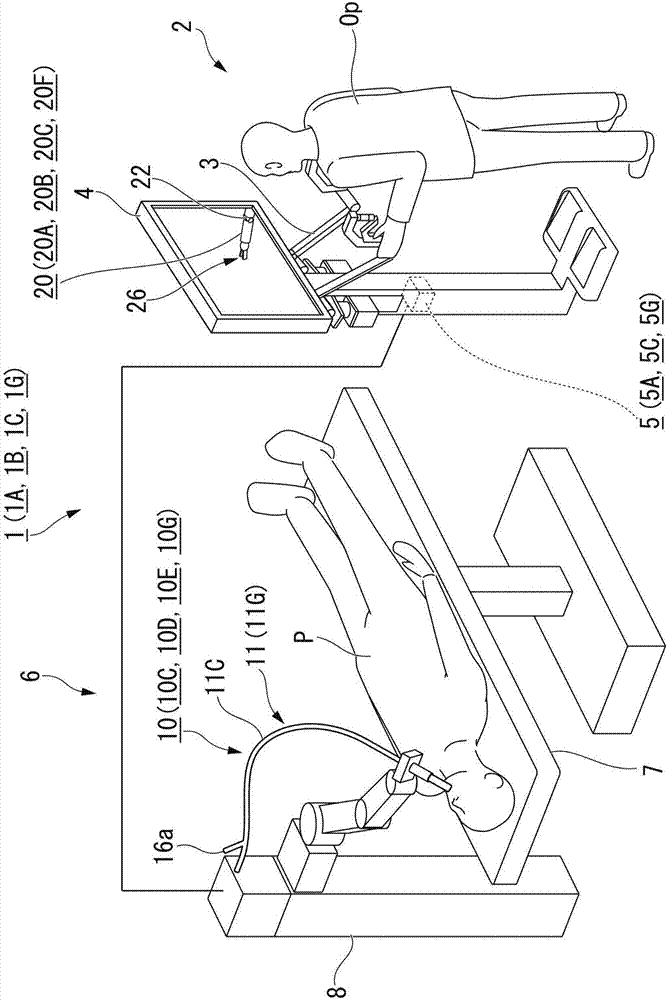
[0062] The robot system used in the method of initializing the robot system according to the first embodiment of the present invention will be described.

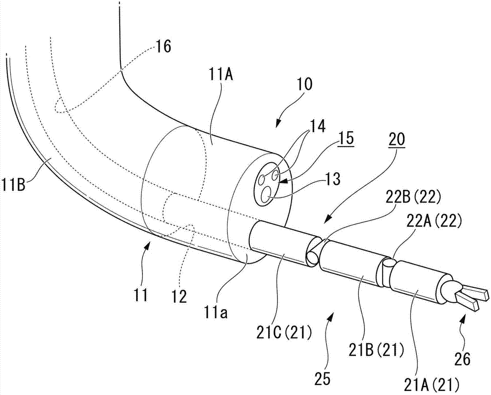
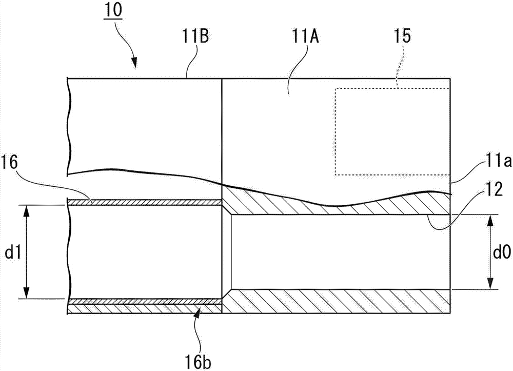
[0063] figure 1 It is a schematic perspective view showing the overall configuration of the robot system used in the method of initializing the robot system according to the first embodiment of the present invention. figure 2 It is a schematic perspective view showing the appearance of a shape defining member and a medical instrument used in the initialization method of the robot system according to the first embodiment of the present invention. Figure 3A It is a partial sectional view showing a shape defining member used in the initialization method of the robot system according to the first embodiment of the present invention. Figure 3B Yes Figure 3A right side view in . Figure 4 It is a schematic system configuration diagram of the medical instrument used in the method of initializing the robot system according t...

no. 2 Embodiment approach

[0232] Next, an initialization method of the robot system according to the second embodiment of the present invention will be described.

[0233] Figure 9 It is a schematic system configuration diagram of a medical instrument used in a method of initializing a robot system according to a second embodiment of the present invention. Figure 10 It is a schematic perspective view showing the configuration of the initial tension applying part of the medical instrument used in the initialization method of the robot system according to the second embodiment of the present invention. Figure 11 It is a schematic cross-sectional view showing the configurations of the driving unit and the driving force relay unit of the medical instrument used in the initialization method of the robot system according to the second embodiment of the present invention. Figure 12 It is a schematic sectional view showing the driving force canceling state of the driving force relay unit of the medical in...

no. 3 Embodiment approach

[0302] Next, an initialization method of the robot system according to the third embodiment of the present invention will be described.

[0303] Figure 15 It is a schematic system configuration diagram of the medical instrument and the shape defining member used in the initialization method of the robot system according to the third embodiment of the present invention. Figure 16A , Figure 16B It is a schematic cross-sectional view showing the relationship between the position of the joint position detection unit and the insertion position of the medical instrument used in the method of initializing the manipulator system according to the third embodiment of the present invention.

[0304] like figure 1 As shown, in the manipulator system 1C used in the initialization method of the manipulator system of this embodiment, instead of the medical instrument 20, the treatment endoscope device 10, and the control unit 5 of the manipulator system 1 in the first embodiment describ...


PUM


Abstract

A method of initializing a manipulator system comprising a medical instrument having a joint for flexion and a shaft-shaped part, a driving force transmission part, a driving part for supplying a driving force, and a driving device capable of switching between a driving force relay state and a driving force release state The force relay unit, the initialization method of the manipulator system has the following process: the joint angle setting process, in the state where the driving force is released, the joint for flexion and the shaft connected by the joint for flexion are inserted into the shape specifying part having the shape specifying part. The pairing of the part sets the joint angle to a predetermined value, and the shape prescribing part makes the joint angle of the joint for flexion a predetermined value; the drive part connection process switches the drive force relay part to the drive force relay state; and the origin In the setting process, after the drive unit connection process is executed, the state of the joint angle of the joint for flexion is associated with the drive origin of the drive unit.

Description

technical field [0001] The invention relates to an initialization method of a manipulator system. [0002] This application claims priority based on Japanese Patent Application No. 2014-032247 for which it applied in Japan on February 21, 2014, and uses the content here. Background technique [0003] Conventionally, from the viewpoint of reducing invasiveness to patients, it is known to insert a treatment instrument into the channel of an endoscope, protrude the treatment instrument from the front end opening of the channel, and perform various treatments under endoscope observation. [0004] For example, Patent Document 1 describes, as such a manipulator system, a medical device including an endoscope that can be manipulated by a bending portion at a distal end, and a treatment instrument inserted into a treatment instrument channel of the endoscope. [0005] In this device, a surgical instrument bending portion operable from the outside is provided at the distal end of th...

Claims


Application Information

Patent Timeline
Patent Type & Authority Patents(China)
IPC IPC(8): B25J9/22A61B1/00A61B34/30B25J17/00G02B23/24
CPCB25J9/1689A61B34/71A61B2034/301A61B34/30A61B1/0051A61B1/018A61B1/00042A61B1/00A61B34/20A61B2034/306A61B34/37A61B2017/00314A61B2017/00327
Inventor 长谷川满彰吉井利博
Owner OLYMPUS CORP
Why Eureka
Try Eureka