Prefabricated radiation floor and manufacturing method and construction method thereof
A technology of manufacturing method and construction method, which is applied to manufacturing tools, floor slabs, ceramic molding machines, etc., can solve the problems of uneven surface temperature distribution, low precision of radiant tube layout, and unsuitable for rapid construction, so as to shorten the construction period of the project. The effect of reducing labor investment and simple and quick on-site construction procedures
- Summary
- Abstract
- Description
- Claims
- Application Information
AI Technical Summary
Problems solved by technology
Method used
Image

Examples
Embodiment 1
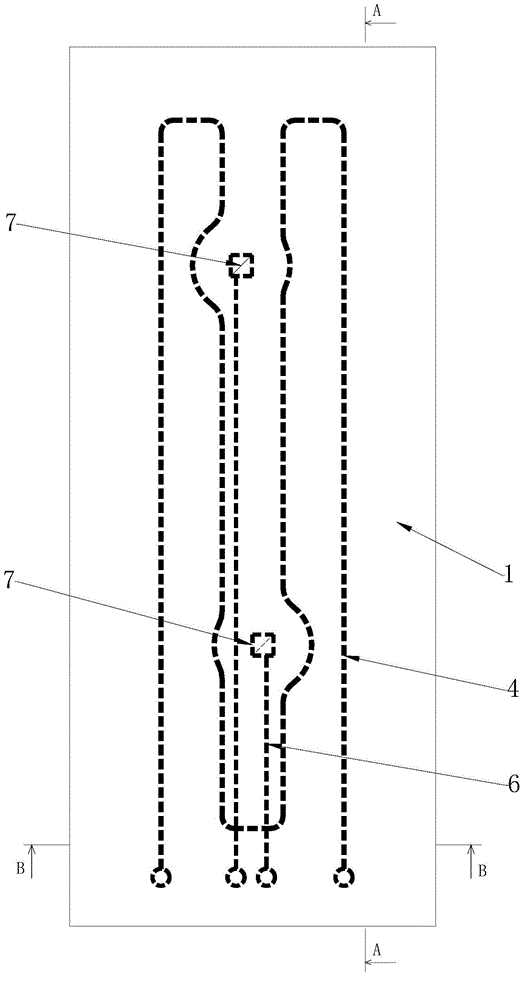
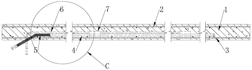
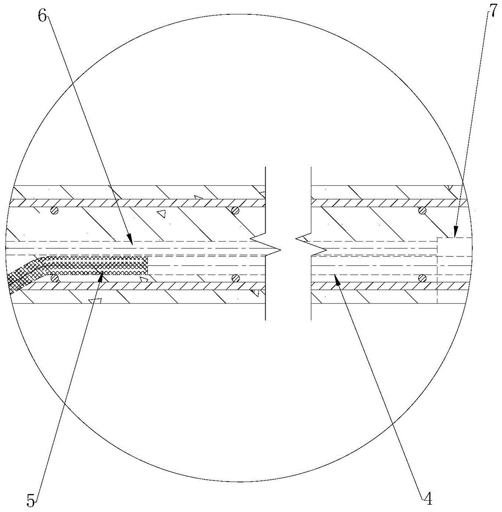
[0044] This embodiment provides a prefabricated radiant floor, such as figure 1 , figure 2 , image 3 , Figure 4 As shown, it includes concrete slab 1 , upper steel bar 2 , lower steel bar 3 and radiant tube 4 . Both the upper-layer reinforcement bars 2 and the lower-layer reinforcement bars 3 are arranged in the concrete slab 1. In this embodiment, the upper-layer reinforcement bars 2 and the lower-layer reinforcement bars 3 both have a mesh structure, and the upper-layer reinforcement bars 2 and the lower-layer reinforcement bars 3 are connected to the upper surface and the lower layer of the concrete slab 1. The surfaces are parallel. The upper layer of reinforcement 2 is located above the lower layer of reinforcement 3 , and there is an interval between the upper layer of reinforcement 2 and the lower layer of reinforcement 3 . The radiation tube 4 is fixed on the lower steel bar 3 , and the radiation tube 4 is located between the upper layer steel bar 2 and the lowe...
Embodiment 2
[0053] This embodiment provides a method for manufacturing a prefabricated radiant floor, including the following steps:
[0054] S10, install formwork, formwork is selected wooden formwork in the present embodiment, and formwork isolating agent is brushed on formwork; Formwork is the box-like shape of upper end opening, comprises bottom surface and four sides, on the surface that formwork contacts with concrete (i.e. formwork the inner surface) to paint the template release agent;
[0055] S20, bind the lower layer of steel bars, and place a pad with a thickness of 15mm under the lower layer of steel bars and above the formwork to ensure that the lower layer of steel bars has a protective layer of 15mm from the bottom surface of the formwork;
[0056] S30. Bind the radiant tube to the steel bar of the lower layer. The radiant tube is located above the steel bar of the lower layer. Make the two ends of the radiant tube protrude out of the formwork, make one end of the wire tub...
Embodiment 3
[0067] This embodiment provides a construction method for a prefabricated radiant floor of the present invention, which includes the following steps:
[0068] S10, hoisting the prefabricated radiant floor slab through the hoisting device;
[0069] S20. Align the hoisted prefabricated radiant floor with the wall, and then fix the prefabricated radiant floor with the wall through the bolts embedded in the wall;
[0070] S30, sealing the joints of two adjacent prefabricated radiant floor slabs with foam glue;
[0071] S40. Connect the radiant tubes between the prefabricated radiant floor slabs; when the radiant tubes are PERT tubes, the connection method is hot-melt connection or using special connectors for PERT tubes; when the radiant tubes are PEXA tubes, the connection method It is connected with special connectors for PEXA pipes.
[0072] S50, performing a pressure test on the connected radiant tube;
[0073] S60. Connect the radiant tube to the water manifold.
[0074] ...
PUM
| Property | Measurement | Unit |
|---|---|---|
| thickness | aaaaa | aaaaa |
Abstract
Description
Claims
Application Information
 - R&D
- Intellectual Property
- Life Sciences
- Materials
- Tech Scout
- Unparalleled Data Quality
- Higher Quality Content
- 60% Fewer Hallucinations
Browse by: Latest US Patents, China's latest patents, Technical Efficacy Thesaurus, Application Domain, Technology Topic, Popular Technical Reports.
© 2025 PatSnap. All rights reserved.Legal|Privacy policy|Modern Slavery Act Transparency Statement|Sitemap|About US| Contact US: help@patsnap.com