
Gas inlet tumble flow control device of gasoline engine

A gasoline engine and control device technology, applied to combustion engines, machines/engines, internal combustion piston engines, etc., can solve the problems of high failure rate, complex system, high manufacturing cost, etc., and achieve low failure rate, simple and effective mechanical structure, and low cost low effect

Inactive Publication Date: 2016-10-05
SUZHOU YINGTEMO AUTOMOBILE TECH CO LTD
View PDF7 Cites 0 Cited by
  • Summary
  • Abstract
  • Description
  • Claims
  • Application Information

AI Technical Summary

Problems solved by technology

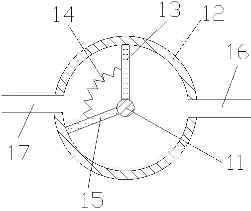
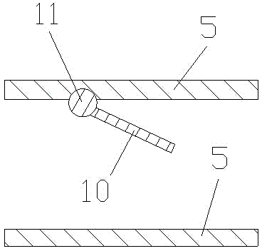
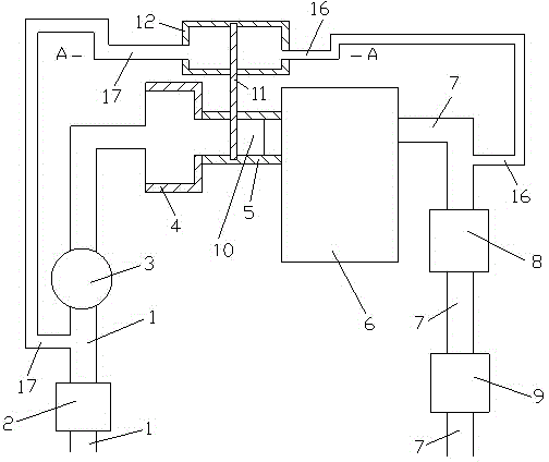
[0004] The technical problem to be solved by the present invention is: in view of the complexity, high manufacturing cost and slightly high failure rate of the current system for adjusting the intake tumble flow of an internal combustion engine, the present invention provides an intake tumble control device for a gasoline engine No electronic control equipment is used, but a simple and effective mechanical structure is used to automatically adjust the tumble flow of the intake air of the internal combustion engine by using the pressure difference

Method used


Image

  • Gas inlet tumble flow control device of gasoline engine
  • Gas inlet tumble flow control device of gasoline engine
  • Gas inlet tumble flow control device of gasoline engine

Examples


Embodiment Construction

[0022] Embodiments of the present invention are described in detail below, examples of which are shown in the drawings, wherein the same or similar reference numerals designate the same or similar elements or elements having the same or similar functions throughout. The embodiments described below by referring to the figures are exemplary only for explaining the present invention and should not be construed as limiting the present invention. On the contrary, the embodiments of the present invention include all changes, modifications and equivalents coming within the spirit and scope of the appended claims.

[0023] In the description of the present invention, it should be understood that the terms "first", "second" and so on are used for descriptive purposes only, and cannot be interpreted as indicating or implying relative importance. In the description of the present invention, it should be noted that unless otherwise specified and limited, the terms "connected" and "connect...


PUM


Abstract

The invention provides a gas inlet tumble flow control device of a gasoline engine. The gas inlet tumble flow control device comprises a control bucket, wherein a control chamber is formed in the control bucket; the control chamber is separated into a first space and a second space which are not communicated with each other; the first space is communicated with an exhausting pipe on a gas inlet side of a catalysis bag through a first connection pipe; and the second space is communicated with a gas inlet pipe between an air filter and a throttle plate through a second connection pipe. The gas inlet tumble flow control device of the gasoline engine has a simple and effective mechanical structure, and gas inlet tumble flow of the engine is adjusted through reasonably utilizing the property of pressure change of the exhausting pipe when an internal-combustion engine works under a high-speed working condition and a low-speed working condition; and any electric control equipment is not used, so that the system is simple in structure, low in cost and low in fault rate, and has a relatively long service life.

Description

technical field [0001] The invention relates to the technical field of internal combustion engines, in particular to an intake tumble control device for a gasoline engine. Background technique [0002] At the beginning of the 20th century, British B. Hopkinson found in the internal combustion engine test that when the air in the cylinder is disturbed, the combustion process can be accelerated Effect, the use of tumble flow to increase the turbulence intensity in the combustion chamber and the use of lean mixture combustion mode, etc., have become the focus of research on spark ignition engines. The air movement in the engine cylinder is transient and complex. From the point of view of the overall movement of the gas macroscopically, it generally appears as an oblique-axis vortex. At this time, the vortex and tumble can be used as two independent components of the oblique-axis vortex. The flow can also increase the turbulence intensity of the air movement in the combustion c...

Claims


Application Information

Patent Timeline
IPC IPC(8): F02B31/06
CPCY02T10/12
Inventor 夏慧鹏陈军何志生
Owner SUZHOU YINGTEMO AUTOMOBILE TECH CO LTD
Learn More