Power transmission line fault hidden risk integrated on-line monitoring method and device

A technology of transmission lines and monitoring devices, applied in the direction of fault locations, etc., can solve the problems of high investment, low efficiency of manual inspection, poor reliability, etc., and achieve the effect of improving efficiency, improving safe operation level, and high working reliability

Active Publication Date: 2016-10-05
WUHAN SUNSHINE POWER SCI & TECH
View PDF7 Cites 30 Cited by
  • Summary
  • Abstract
  • Description
  • Claims
  • Application Information

AI Technical Summary

Problems solved by technology

[0005] In order to solve the problems of low efficiency of manual inspection of hidden faults of transmission lines, high investment and poor reliability of traditional monitoring methods, a power transmission The comprehensive on-line monitoring method and device for line fault hidden dangers are...

Method used


Image

  • Power transmission line fault hidden risk integrated on-line monitoring method and device
  • Power transmission line fault hidden risk integrated on-line monitoring method and device
  • Power transmission line fault hidden risk integrated on-line monitoring method and device

Examples


Embodiment 1

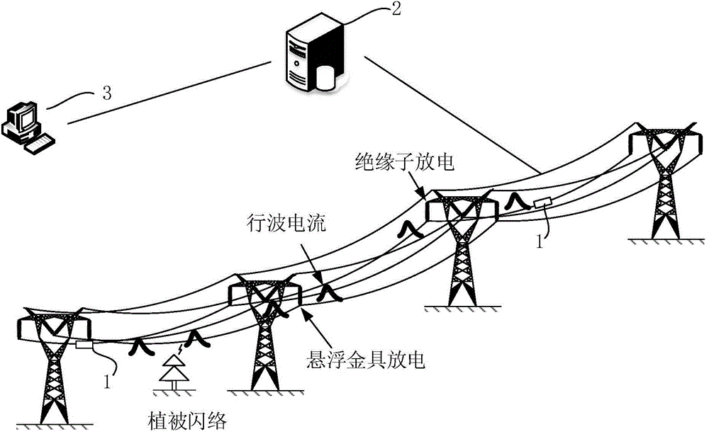
[0046] Such as figure 1 Shown is a structural schematic diagram of a comprehensive on-line monitoring device for transmission line fault hidden dangers. The comprehensive on-line monitoring device for hidden dangers of transmission line failure includes a data collection terminal 1, a data center station 2 and a remote access terminal 3. The data acquisition terminal 1 is installed on the transmission line with an installation interval of 10 to 20 kilometers. Each installation point contains at least three data acquisition terminals 1, which are distributed and installed on the three-phase conductors of the transmission line A, B, and C; the system adopts active triggering Cooperate with the two mechanisms of timing reporting, usually in the timing reporting mode, according to the self-set upload time and the amplitude range of hidden fault currents, collect hidden traveling wave currents and corresponding GPS clock information, and upload them to the data center in real time ...

Embodiment 2

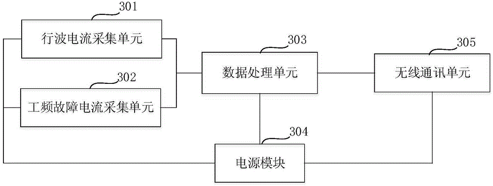
[0060] Such as image 3 Shown is a schematic structural diagram of the data collection terminal 1 of the present invention. The data acquisition terminal 1 includes a traveling wave current acquisition unit 301 , a power frequency fault current acquisition unit 302 , a data processing unit 303 , a power module 304 and a wireless communication unit 305 . The traveling wave current acquisition unit 301 and the power frequency fault current acquisition unit 302 respectively collect the traveling wave current and the power frequency fault current generated by the hidden discharge of the transmission line fault, the data processing unit 303 performs data processing on the collected information, and sends it to In the data center station 2, the power supply module 304 provides energy supply for each unit.

[0061] The core part of the traveling wave current acquisition unit 301 is a Rogowski coil with a magnetic core and a power frequency trap circuit. The Rogowski coil is general...

Embodiment 3

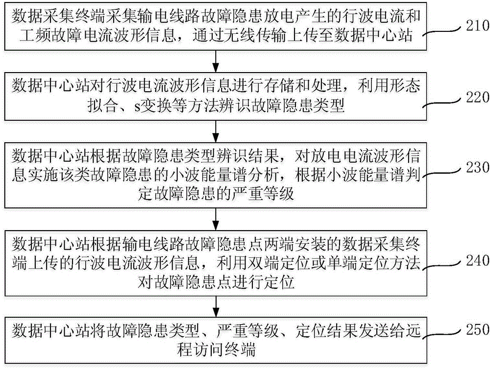
[0069] Such as Image 6 Shown is a flow chart of the second comprehensive online monitoring method for transmission line fault hidden dangers. Compared with the monitoring method 1, the monitoring method 2 of this embodiment also includes the step of judging the severity level of the transmission line fault hidden danger according to the traveling wave current and the power frequency fault current.

[0070] This monitoring method includes:

[0071] Step 210, the data collection terminal 1 collects the traveling wave current and power frequency fault current waveform information generated by the hidden discharge of the transmission line fault, and uploads it to the data center station 2 through wireless transmission;

[0072] Step 220, the data center station 2 stores and processes the information of the traveling wave current waveform, and uses methods such as shape fitting and s-transformation to identify the types of potential faults;

[0073] Step 230, the data center sta...


PUM


Abstract

The invention relates to a method and device for comprehensive on-line monitoring of hidden dangers of transmission line faults, which are installed on the transmission line to detect faults such as cracking of composite insulators, suspended discharge of fittings, vegetation flashover, pollution of insulators, and ice flashover of insulators, etc., which occur during long-term operation of the line. The traveling wave current signal generated by the hidden danger discharge is monitored online; for the collected traveling wave current waveform information, firstly, the type of the hidden trouble is identified by means of shape fitting and s-transformation; then the severity level of the hidden trouble is determined according to the wavelet energy spectrum; finally Locate the hidden trouble point by using double-end positioning or single-end positioning method. The invention creatively proposes to use the discharge current when a hidden trouble occurs as the detection object to realize the identification, positioning and early warning of the hidden trouble, and solves the problems of low efficiency, high cost and low reliability of traditional monitoring methods mainly based on manual inspection at present. Problems, prevent transmission line failures before they happen, and improve the stable operation level of the power grid.

Description

technical field [0001] The invention relates to the related technical field of on-line monitoring of transmission lines, in particular to a method and device for comprehensive on-line monitoring of potential faults of transmission lines, which are mainly used in the diagnosis and early warning of potential faults of transmission lines. Background technique [0002] During the operation of transmission lines, in addition to sudden faults such as lightning strikes and floating objects, there are also a large number of "gradual" faults in operation and maintenance, such as composite insulator cracking faults caused by long-term running time, and long-term suspension discharge of fittings. Breakage and falling off, long-term pollution accumulation of insulators and trips, high tree growth leading to flashover trips, and icing of insulators lead to flashover trips, etc., which seriously threaten the safe and stable operation of the power grid. In order to avoid these liability ac...

Claims


Application Information

Patent Timeline
IPC IPC(8): G01R31/08
Inventor 钱冠军余刚华
Owner WUHAN SUNSHINE POWER SCI & TECH
Why Eureka
Try Eureka