Leakage circuit breaker
A leakage circuit breaker and circuit technology, applied in circuit devices, emergency protection circuit devices, electrical components, etc., can solve problems such as power circuit failures of leakage circuit breakers, and achieve the effect of preventing failures
- Summary
- Abstract
- Description
- Claims
- Application Information
AI Technical Summary
Problems solved by technology
Method used
Image

Examples
Embodiment approach 1
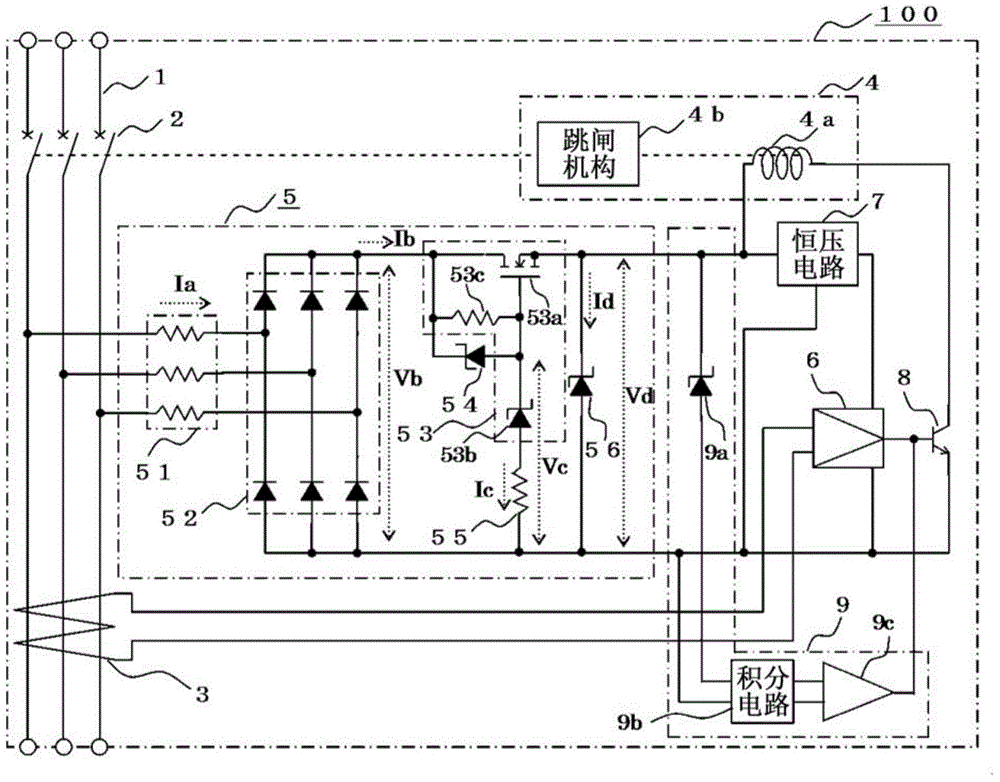
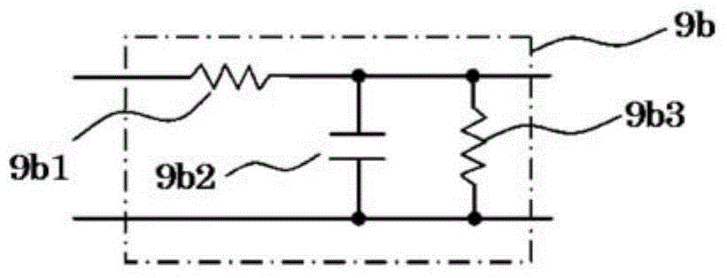
[0023] figure 1 It is a circuit diagram showing the structure of an earth leakage circuit breaker using a power supply circuit according to Embodiment 1 of the present invention, figure 2 yes means figure 1 A circuit diagram showing an example of the details of the integrating circuit.
[0024] exist figure 1 Among them, the leakage circuit breaker 100 has: a switch contact 2, which makes the AC circuit 1 on and off; a leakage detection circuit 6, which is connected to the zero-phase-sequence converter 3 inserted in the AC circuit 1, that is, the leakage current detector, And based on the detection signal of the zero-phase-sequence converter 3, the leakage is detected; the tripping device 4 has a tripping coil 4a and a tripping mechanism 4b, wherein the tripping coil 4a is based on the output signal of the leakage detection circuit 6, via a switch (switching) unit 8 to generate electromotive force, the tripping mechanism 4b separates and drives the switch contact 2 when...
Embodiment approach 2
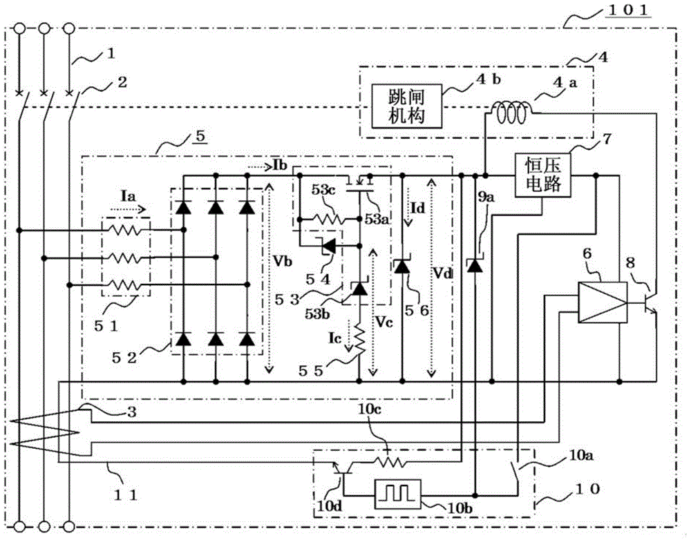
[0058] image 3 It is a circuit diagram showing the structure of an earth leakage circuit breaker using a power supply circuit according to Embodiment 2 of the present invention, Figure 4 yes means image 3 A block diagram showing an example of the details of the leakage detection circuit.
[0059] The leakage circuit breaker 101 of this embodiment is provided with the leakage test circuit 10 including the overvoltage detection circuit instead of the overvoltage detection circuit 9 of the first embodiment, and achieves various effects similar to those of the first embodiment described above.
[0060] exist image 3 Among them, the leakage test circuit 10 of the leakage circuit breaker 101 is composed of the following components: the 4th Zener diode 9a, the cathode of which is connected to the cathode of the 3rd Zener diode 56; the test switch 10a, one end of which is connected to the first constant voltage circuit 7 The output connection of the other end is connected with th...
Embodiment approach 3
[0083] Figure 5 It is a circuit diagram showing the structure of the earth leakage circuit breaker for DC using the power supply circuit of Embodiment 3 of this invention.
[0084] exist Figure 5 In the earth leakage circuit breaker 102 of this embodiment, the overvoltage detection circuit 9 of Embodiment 1 is applied to the earth leakage circuit breaker for DC. In the first embodiment, the zero-phase-sequence converter is used as the leakage current detector, but the fluxgate sensor 31 capable of detecting a direct current leakage current is used as the leakage current detector, and various functions similar to those in the above-mentioned first embodiment are realized. Effect.
[0085] Such as Figure 5 As shown, the fluxgate sensor 31 has: an annular iron core 31a, into which the DC circuit 11 is inserted; a coil 31b, which is wound on the iron core 31a; 31a applies a voltage so as to saturate the magnetic flux density of the coil 31b while reversing the direction; an...
PUM
| Property | Measurement | Unit |
|---|---|---|
| Resistance | aaaaa | aaaaa |
Abstract
Description
Claims
Application Information
 - R&D
- Intellectual Property
- Life Sciences
- Materials
- Tech Scout
- Unparalleled Data Quality
- Higher Quality Content
- 60% Fewer Hallucinations
Browse by: Latest US Patents, China's latest patents, Technical Efficacy Thesaurus, Application Domain, Technology Topic, Popular Technical Reports.
© 2025 PatSnap. All rights reserved.Legal|Privacy policy|Modern Slavery Act Transparency Statement|Sitemap|About US| Contact US: help@patsnap.com