A signal transmission method and device

A technology of signal transmission and transmitting antenna, which is applied in the field of communication, can solve the problems of high complexity, offset power reduction, weakening, etc., and achieve the effect of eliminating self-interference, simple implementation, and eliminating interference

Active Publication Date: 2019-09-17
DATANG MOBILE COMM EQUIP CO LTD
View PDF3 Cites 0 Cited by
  • Summary
  • Abstract
  • Description
  • Claims
  • Application Information

AI Technical Summary

Problems solved by technology

[0007] For the full-duplex wireless communication system with the millimeter wave band as the carrier frequency, in the millimeter wave band with a frequency range of 30-300 GHz, many scenarios require the use of multi-element antenna arrays and beamforming technology to compensate for its high propagation loss. Radio frequency and digital two-level interference cancellation technology, the interconnection of the radio frequency part between the transmitting antenna array of m array elements and the receiving antenna array of n array elements will result in an m by n matrix, and the complexity of the digital part is also the same as that of the transmitting antenna The product of the number of digital channels of the array and the receiving antenna array is directly proportional. Obviously, the complexity and cost of the two are too high to be practical
However, the self-interference cancellation is carried out by using the method of transmitting signals from the transmitting antenna at the phase difference π / 2 of the receiving antenna, and the effect of self-interference cancellation will be weakened due to the inaccurate position of the antenna; the method of balun passive cancellation, 5 MHz (Mega Hertz, MHz) bandwidth signals can offset 52 decibels (dB), while 100MHz signals can offset 40dB of transmitted signals, and the offset power decreases as the signal bandwidth increases, and the effect will be worse for millimeter waves
[0008] To sum up, in the full-duplex wireless communication system with the millimeter-wave band as the carrier frequency, the multi-element antenna array is used to compensate the high propagation loss caused by the high carrier frequency by using the beamforming technology, but the full-duplex The self-interference elimination method of industrial wireless communication system is difficult to apply when eliminating the self-interference of multi-element antenna array

Method used


Image

  • A signal transmission method and device
  • A signal transmission method and device
  • A signal transmission method and device

Examples


Embodiment Construction

[0030] The specific implementation manners of a signal transmitting method and device provided in the embodiments of the present invention will be described in detail below with reference to the accompanying drawings.

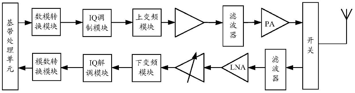
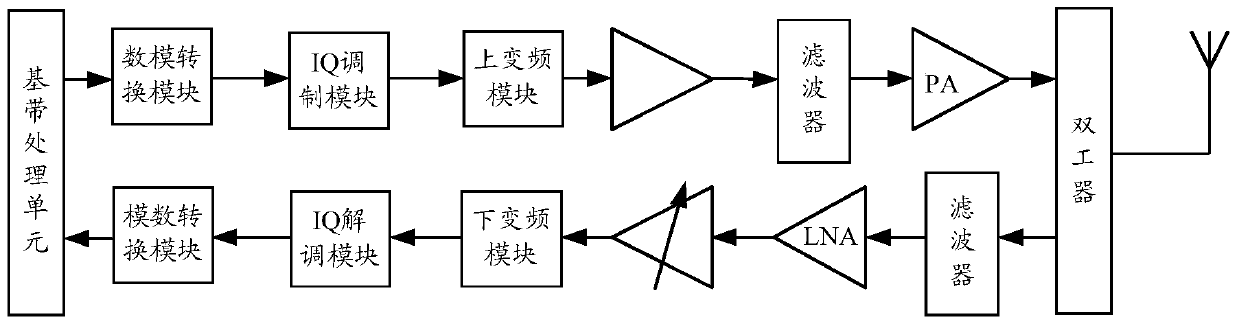
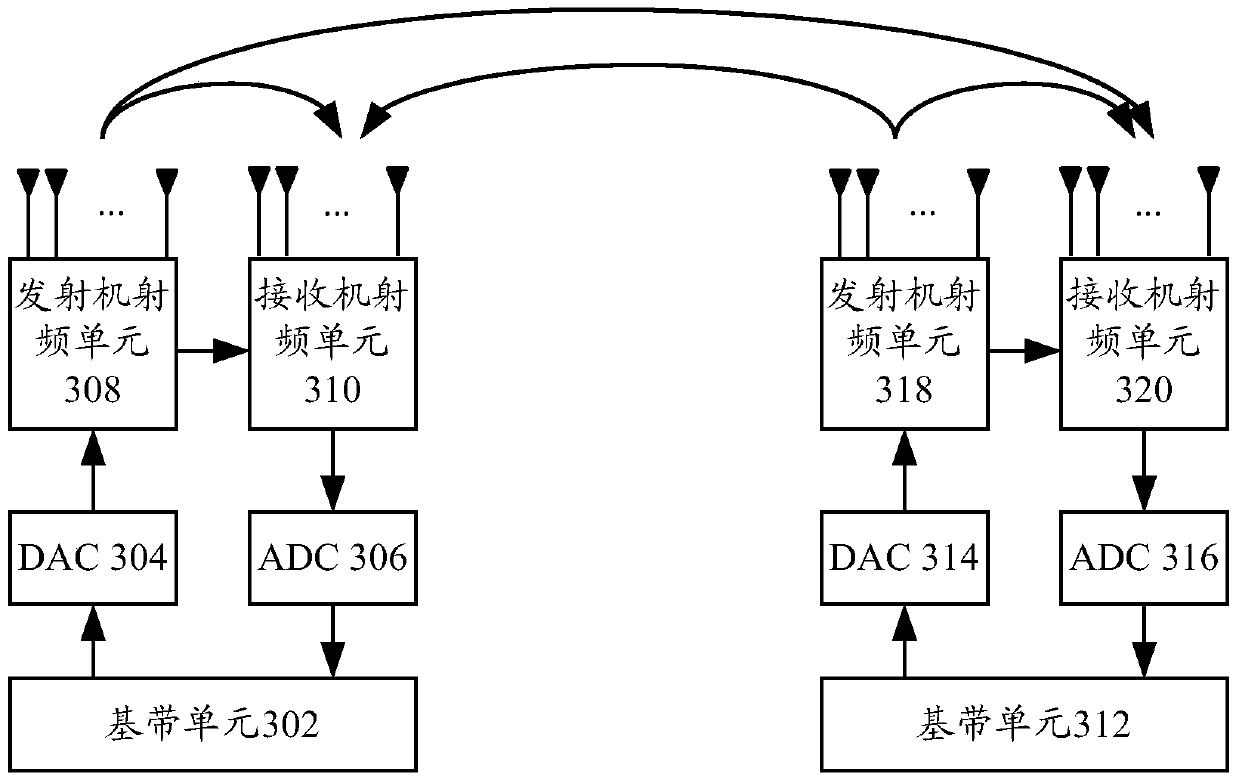
[0031] The signal transmitting method provided by the embodiment of the present invention is applied between multi-element antenna arrays in a full-duplex wireless communication system, especially in a full-duplex wireless communication system with millimeter wave band as the carrier frequency. The transmitting antenna array and the receiving antenna array mentioned in the embodiment of the present invention are the transmitting antenna array and the receiving antenna array located in the same transceiver, for example: the transmitting antenna array and the receiving antenna array located in the same transceiver of the base station, the user Device An array of transmit antennas and an array of receive antennas in the same transceiver. The present invention will...


PUM


Abstract

The invention discloses a signal emission method and device. The method and device are applied to a full-duplex wireless communication system in the carrier frequency of millimeter waveband to eliminate interference of an emission signal of an emission antenna array in a reception signal of a reception antenna array of the same transceiver as well as self interference between the emission antenna array and the reception antenna array. The signal emission method comprises that the position of the reception antenna array is determined; and the emission antenna array emits signals by using a wave beam shaping technology. When the signal is emitted in the wave beam shaping technology, the position of the reception antenna array is null position, and the emission antenna array and the reception antenna array are placed in the same transceiver.

Description

technical field [0001] The present invention relates to the field of communication technologies, in particular to a signal transmitting method and device. Background technique [0002] Full-duplex (Full-duplex) technology is a new technology that has attracted widespread attention in recent years. In the case of applying full-duplex technology, full-duplex wireless communication systems and frequency division duplex (Frequency Division Duplex, FDD) or Compared with the Time Division Duplex (TDD) system, since the transmitted signal and the received signal are carried out at the same frequency at the same time, the transmitted signal will interfere with the locally received received signal. Specifically: [0003] figure 1 shows a schematic structural diagram of a transceiver in a TDD wireless communication system, as figure 1 As shown, in the time division duplex TDD mode, signals are sent and received at different times at the same frequency, and the transmit signal link a...

Claims


Application Information

Patent Timeline
Patent Type & Authority Patents(China)
IPC IPC(8): H04B7/06H04B1/525
Inventor 王蒙军
Owner DATANG MOBILE COMM EQUIP CO LTD
Why Eureka
Try Eureka