Timing Synchronization Method in Physical Layer

A timing synchronization, physical layer technology, applied in the field of broadcasting and communication, can solve the problems of inability to store the whole frame of data, low signal-to-noise ratio, carrier frequency offset effect, etc., to achieve the effect of complexity and low signal-to-noise ratio

Active Publication Date: 2019-04-30
SHANGHAI NAT ENG RES CENT OF DIGITAL TELEVISION
View PDF3 Cites 0 Cited by
  • Summary
  • Abstract
  • Description
  • Claims
  • Application Information

AI Technical Summary

Problems solved by technology

[0006] The problem solved by the present invention is that the existing synchronous detection method using known information is seriously affected by the carrier frequency offset, especially for a long frame structure such as DVB_T2, it is impossible to store the entire frame data, then the existing synchronization detection method using delay sliding correlation that can resist frequency offset cannot achieve the performance of lower SNR (for example, below -10dB)

Method used


Image

  • Timing Synchronization Method in Physical Layer
  • Timing Synchronization Method in Physical Layer
  • Timing Synchronization Method in Physical Layer

Examples


Embodiment 1

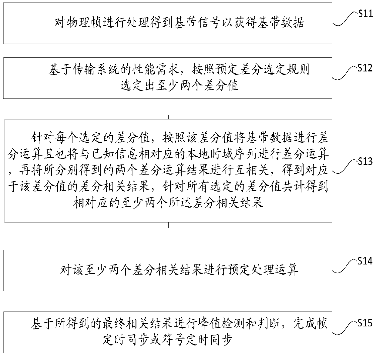
[0027] An embodiment of the present invention provides a timing synchronization method in a physical layer. Such as figure 1 What is shown is a schematic flowchart of the timing synchronization method in the specific implementation manner of the present invention.

[0028] refer to figure 1 , in this embodiment, the timing synchronization method is suitable for a transmission system that utilizes known information for transmission. The transmission system is a broadcasting system or a communication system.

[0029] If the transmission system is a multi-carrier system, its preamble symbols contain known information. For example, the preamble symbol is generated based on the OFDM symbol, and pilots are inserted into certain subcarriers in the OFDM symbol, then the preamble symbol contains known information. Alternatively, the preamble symbol is based on the superposition of two time domain signals in the time domain, one is a time domain signal for signaling and the other is...

Embodiment 2

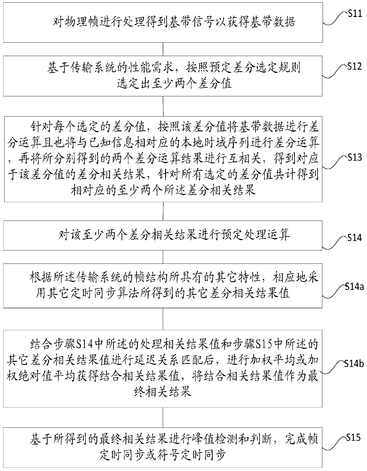
[0089] In addition to the technical solution of using at least two differential values ​​for positioning synchronization in Embodiment 1 and Embodiment 2, the inventors also found that the process of using a single differential value for positioning synchronization in the prior art can also be compared with other timing synchronization Other differential correlation results obtained by the algorithm R other,m Combined, it is used to solve the problems caused by positioning synchronization with a single difference value, such as only generating a set of difference correlation results, which cannot obtain very robust performance.

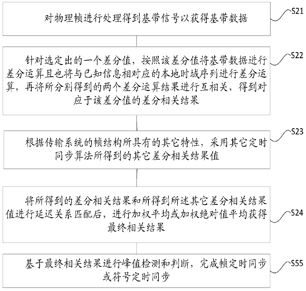
[0090] The present invention also proposes a timing synchronization method in the physical layer, image 3 It is a schematic flowchart of the timing synchronization method in Embodiment 2 of the specific implementation manner of the present invention.

[0091] refer to image 3 , the timing synchronization method in Embodiment 2, which is used in a ...


PUM


Abstract

The present invention provides a timing synchronization method in a physical layer. The method is characterized in that a differential-related result related to n sets of sliding is obtained based on baseband data and a local time domain sequence after being subjected to differential operation, and N different differential values. After the further treatment, the noise is filtered out, so that a relatively low signal-to-noise ratio is obtained. Meanwhile, the number N of the N different differential values is determined based on the performance requirements of a transmission system, so that the balance of the complexity is realized. In addition, for the condition of a single differential value, a differential-related result can also be obtained based on baseband data and a local time domain sequence after being subjected to differential operation. After that, in combination with other differential-related results (Rother, m), the weighted average calculation or the weighted absolute value average calculation is conducted after the delay relationship matching process. In this way, the frame timing synchronization or the symbol timing synchronization is realized. The timing synchronization method provided in the invention skillfully utilizes the known information and filters out the noise, so that the obtained signal-to-noise ratio is relatively low. Meanwhile, the balance of the complexity is realized. Moreover, the method has the advantages of frequency offset resistance and good robust performance.

Description

technical field [0001] The invention belongs to the technical field of broadcasting and communication, and in particular relates to a timing synchronization method in a physical layer. Background technique [0002] In broadcasting systems and communication systems, the receiving end usually needs to perform symbol timing synchronization or frame timing synchronization on physical layer signals to find the initial position of the data frame so as to extract data blocks for demodulation. [0003] For example, in the DVB_T2 system, there is a preamble symbol in each frame structure, and the receiver needs to detect the position where the preamble symbol appears before performing subsequent processing. Another example is the DTMB system. Each frame structure has a PN frame header. The PN frame header is transmitted first, and then the system information and data segment are transmitted. The receiving end needs to detect the position of the PN frame header before proceeding to th...

Claims


Application Information

Patent Timeline
Patent Type & Authority Patents(China)
IPC IPC(8): H04L27/26H04N21/61
Inventor 黄戈邢观斌张文军徐洪亮管云峰
Owner SHANGHAI NAT ENG RES CENT OF DIGITAL TELEVISION
Why Eureka
Try Eureka