Power device parallel cooling structure and motor controller applying same

A technology of power device and cooling structure, applied in motor control, control system, cooling/ventilation/heating transformation, etc., can solve the problems of low chip temperature, high chip temperature, redundant heat dissipation conditions of high-power devices, etc. The effect of changing and smooth flow

Active Publication Date: 2016-10-05
上海汽车电驱动有限公司 +1
View PDF5 Cites 6 Cited by
  • Summary
  • Abstract
  • Description
  • Claims
  • Application Information

AI Technical Summary

Problems solved by technology

[0003] At present, there are at least the following problems in the cooling system of high-power devices in series: when using the same cooling channel to cool multiple high-power devices of the same working condition, the chip temperature of the high-power devices near the entrance of the cooling channel will be relatively low. Low, while the chip temperature of high-power devices near the exit of the cooling channel is relatively high
If the temperature difference between the two is large, and the chip with a relatively high temperature needs to be detected during temperature detection, the performance of high-power devices near the entrance cannot be fully utilized.
However, when using the same cooling channel to cool multiple high-power devices with different capacitance values, the heat dissipation conditions of the high-power devices with large losses are tight, while the heat dissipation conditions of high-power devices with small losses are redundant, then The heat dissipation performance of the cooling system cannot be fully utilized

Method used


Image

  • Power device parallel cooling structure and motor controller applying same
  • Power device parallel cooling structure and motor controller applying same
  • Power device parallel cooling structure and motor controller applying same

Examples


Embodiment 1

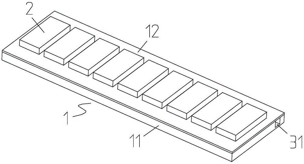
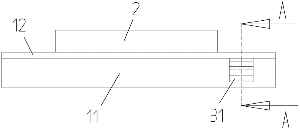
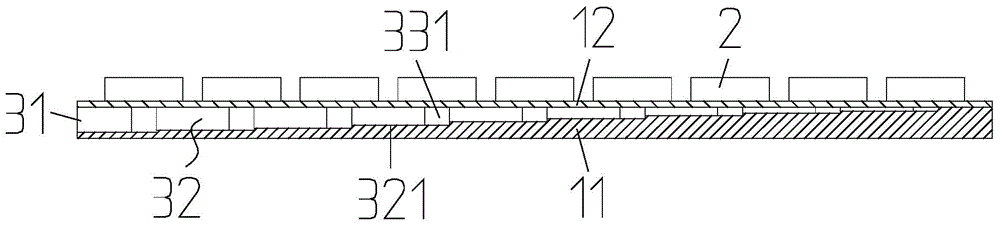
[0034] Embodiment one: if figure 1 , figure 2 , image 3 , Figure 4 , Figure 5 and Figure 6 As shown, this embodiment is a parallel cooling structure for power devices, including a heat dissipation base 1 and several power devices 2, and several power devices 2 are installed on the heat dissipation base 1 at intervals, and a heat dissipation water channel is arranged inside the heat dissipation base 1 3. The heat dissipation channel 3 includes a water inlet 31, a water inlet channel 32, several branch channels 33, an outlet channel 34 and a water outlet 35. The water inlet 31 is connected to the water inlet channel 32, and the water outlet 35 is connected to the water outlet channel 34. Several The tributary waterways 33 are arranged side by side between the water inlet 32 ​​and the water outlet 34, and the water inlet 32 ​​and the water outlet 34 are connected in parallel by several tributary waterways 33. The cross-sectional area of ​​the water inlet 32 ​​starts from...

Embodiment 2

[0051] Embodiment two: if Figure 8 and Figure 9 As shown, the difference from Embodiment 1 is that: a step portion 122 protrudes downward from the bottom surface of the cover plate 12, and the height of the step portion 122 extending downward from the water inlet 31 gradually becomes larger, and the step portion 122 extends into the Inside the water inlet channel 32 , and the step portions 122 and the diverging steps 6 are arranged in a staggered interval, so that the cross-sectional area of ​​the water inlet channel 32 gradually decreases from the water inlet 31 .

[0052] The parallel cooling structure of the power devices in the embodiment will be further described by means of a simulation test. In this embodiment, the number of branch water channels 33 is also nine.

[0053] Simulation test:

[0054] 1. Material property: 25℃ water.

[0055] 2. Boundary conditions and solution settings

[0056] The inlet flow rate is 30L / min, and the average relative pressure at the ...

Embodiment 3

[0065] Embodiment three: as Figure 10 and Figure 11 As shown, this embodiment is a motor controller, including a controller box 4, a heat dissipation base 1, a control circuit board 5 and several power modules 2, the heat dissipation base 1 is arranged inside the controller box 4, and several power devices 2 They are respectively arranged at intervals on the heat dissipation base 1, and the heat dissipation water channel 3 is arranged in the heat dissipation base 1, and the control circuit board 5 is installed in the controller box 4, and each power module 2 is electrically connected with the control circuit board 5. Together, the cooling channel 3 includes a water inlet 31, a water inlet channel 32, several branch channels 33, an outlet channel 34 and a water outlet 35, the water inlet 31 communicates with the water inlet channel 32, the water outlet 35 communicates with the water outlet channel 34, and several The tributary waterways 33 are arranged side by side between t...


PUM


Abstract

The invention discloses a power device parallel cooling structure and a motor controller applying the same. The power device parallel cooling structure comprises a heat dissipation base and a plurality of power devices, wherein the plurality of power devices are installed on the heat dissipation base at intervals, and a heat dissipation water channel is arranged in the heat dissipation base. The power device parallel cooling structure is characterized in that the heat dissipation water channel comprises a water inlet, a water inlet channel, a plurality of branch water channels, a water outlet channel and a water outlet, wherein the water inlet is communicated with the water inlet channel, the water outlet is communicated with the water outlet channel, the plurality of branch water channels are arranged side by side between the water inlet channel and the water outlet channel, the water inlet channel is connected with the water outlet channel in parallel by means of the plurality of branch water channels, and the cross sectional area of the water inlet channel is decreased gradually from the water inlet, thereby enabling temperature difference of different high-power devices to be minimum, giving full play to the performance of the high-power devices and a cooling system, and meeting requirements of integration and miniaturization of new-energy products.

Description

Technical field: [0001] The invention relates to a parallel cooling structure of power devices and a motor controller applied thereto, belonging to the technical field of motor vehicles. Background technique: [0002] In the field of new energy, the demand for the capacitance of high-power devices such as IGBTs is increasing year by year, which puts forward higher requirements for the heat dissipation performance of the cooling system. If the heat generated by the high-power device cannot be dissipated in time, the high-power device cannot work normally. In addition, the market has put forward requirements for integration, integration and miniaturization of new energy products such as motor controllers and motors. When multiple high-power devices are used and arranged closely, it is necessary to pass high-power devices The heat flux density of the heat sink is constantly increasing to meet its heat dissipation requirements. [0003] At present, there are at least the follo...

Claims


Application Information

Patent Timeline
Patent Type & Authority Applications(China)
IPC IPC(8): H05K7/20H02P29/00
CPCH05K7/20
Inventor 焦兵锋
Owner 上海汽车电驱动有限公司
Why Eureka
Try Eureka