De-dusting demisting device

A technology of demisting device and dedusting component, which is applied in the direction of combination device, using liquid separating agent, dispersing particle separation, etc., can solve the problems of no fine dust removal, small dewatering specific area, low dewatering efficiency, etc., and achieves good absorption effect, The effect of short flow line and high dewatering and dust removal efficiency

Active Publication Date: 2016-10-12
MCC CAPITAL ENGINEERING & RESEARCH
View PDF7 Cites 1 Cited by
  • Summary
  • Abstract
  • Description
  • Claims
  • Application Information

AI Technical Summary

Problems solved by technology

The existing dehydration tower adopts the first-stage cyclone cyclone dehydration method, which has a small dehydration specific area, low dehydration efficiency, and does not have the function of fine dust removal

Method used


Image

  • De-dusting demisting device
  • De-dusting demisting device
  • De-dusting demisting device

Examples


Embodiment Construction

[0059] The above-mentioned technical features and advantages of the present invention will be clearly and completely described below in conjunction with the accompanying drawings. Apparently, the described embodiments are only some, not all, embodiments of the present invention.

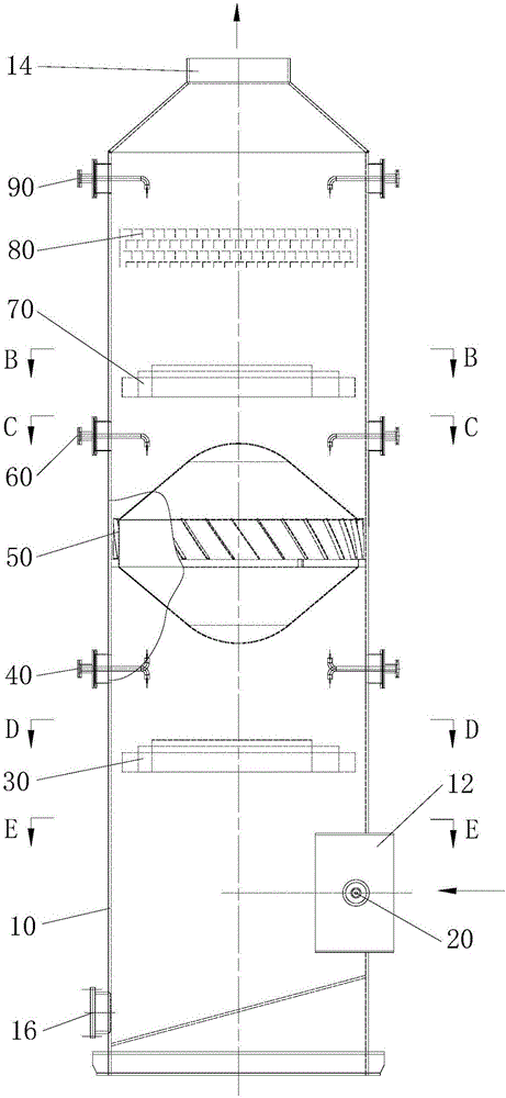
[0060] see Figure 1 to Figure 5 As shown, the present invention proposes a dust and mist removal device. The dust and mist removal device includes a vertically arranged cylinder body 10. The cylinder body 10 has an inner cavity. The cylinder body 10 is provided with an inlet 12 and an outlet 14, and the inlet 12 is for flue gas to enter. Inner cavity, the outlet 14 outputs the purified gas in the inner cavity; the inlet 12 is arranged on the side wall of the cylinder 10, and is located below the outlet 14, and a sewage pipe 16 is arranged below the inlet 12, and the sewage pipe 16 communicates with the inner cavity and External sedimentation tank.

[0061] The dust and mist removal device also incl...


PUM

PropertyMeasurementUnit
thicknessaaaaaaaaaa
lengthaaaaaaaaaa
widthaaaaaaaaaa

Abstract

The invention provides a de-dusting demisting device which comprises a vertically arranged drum, wherein the drum is provided with an inner cavity; an inlet and an outlet are formed on the drum; smoke enters the inner cavity through the inlet; gas purified in the inner cavity can be outputted from the outlet; the inlet is formed on a side wall of the drum and is located under the outlet; a blow-off pipe which is used for communicating the inner cavity with the outside settling pond is arranged under the inlet. The de-dusting demisting device further comprises a pre-misting spray gun and a purifying mechanism, wherein the pre-misting spray gun is arranged at the inlet; the purifying mechanism is arranged in the drum; the purifying mechanism comprises a first level compound baffle dewatering de-dusting component, a first level spraying component, a rotating accelerating dewatering de-dusting component, a second level spraying component, a second level compound baffle dewatering de-dusting component and a baffle plate dewatering demisting component which are fixedly arranged between the inlet and the outlet in turn from bottom to top. The de-dusting demisting device can efficiently remove dust and finely dewater, the gas flow line is short and the pressure loss is low.

Description

technical field [0001] The invention relates to the technical field of dust removal and purification, in particular to a device for removing dust and mist from high-temperature gas containing smoke. Background technique [0002] Oxygen-blowing smelting is used in oxygen converter steelmaking. During the blowing process, high-temperature gas containing a large amount of smoke and dust will be produced, and the dust concentration can reach as high as 100 grams per standard cubic meter (g / Nm 3 ) ~ 150 grams per standard cubic meter, the temperature is as high as 1450 degrees Celsius. Dust-laden high-temperature gas needs to be washed with large-flow water mist at the first-stage venturi tube and the second-stage venturi tube to remove most of the dust in the flue gas and reduce the dust concentration to 100 mg per standard cubic meter (mg / N m 3 ), the temperature drops to the dew point temperature, at this time the humidity of the flue gas reaches saturation, and a large amo...

Claims


Application Information

Patent Timeline
Patent Type & Authority Applications(China)
IPC IPC(8): B01D50/00B01D47/06
CPCB01D47/06B01D50/00
Inventor 刘革任乐瞿华周向张传波
Owner MCC CAPITAL ENGINEERING & RESEARCH
Why Eureka
Try Eureka