Efficient boiler flue gas treatment device

A technology for boiler flue gas and treatment device, which is used in gas treatment, transportation and packaging, dispersed particle filtration, etc., can solve the problems of large overall energy consumption, complex structure, and inability to purify flue gas, so as to protect the living environment and reduce atmospheric pollution. Good pollution and purification effect

Inactive Publication Date: 2016-10-12
HARBIN JINJING BOILER
View PDF0 Cites 8 Cited by
  • Summary
  • Abstract
  • Description
  • Claims
  • Application Information

AI Technical Summary

Problems solved by technology

[0003] At present, the flue gas purification methods for coal-fired boilers are mainly single desulfurization or denitrification or dust removal, which obviously cannot completely purify the flue gas
Although there are many desulfurization and denitrification technologies on the

Method used


Image

  • Efficient boiler flue gas treatment device

Examples


Embodiment 1

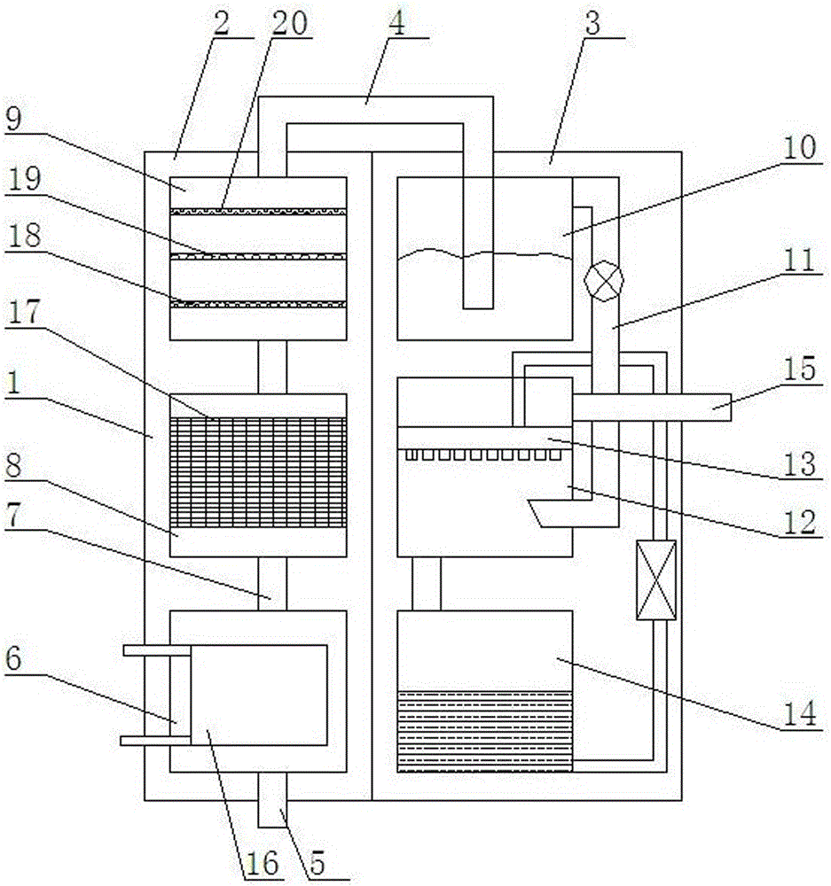
[0018] as shown in the picture 1 As shown, a high-efficiency boiler flue gas treatment device, including a treatment box 1 , left chamber 2 , right chamber 3 , the process box 1 The interior consists of the left box chamber 2 with right chamber 3 constitute, the left box chamber 2 air tube 4 Connect to the right chamber 3 top; said left chamber 2 Bottom unit intake pipe 5 , the left box compartment 2 Internal bottom device cooling chamber 6 , the cooling chamber 6 Bottom connection intake pipe 5 ; The cooling chamber 6 smoke pipe 7 Before connecting the filter cavity 8 ; The front filter cavity 8 smoke pipe 7 filter cavity after connection 9 ; the right chamber 3 Internal upper device denitrification chamber 10 ; The denitrification chamber 10 air tube 4 filter cavity after connection 9 ; The denitrification chamber 10 upper right through the snorkel 11 Connect the lower desulfurization chambe...

Embodiment 2

[0020] as shown in the picture 1 As shown, the cooling chamber 6 Internal device plate heat exchanger 16 。

Embodiment 3

[0022] as shown in the picture 1 As shown, the front filter cavity 8 The internal device is equipped with multi-layer titanium wire weaving filter screen 17 。


PUM


Abstract

An efficient boiler flue gas treatment device comprises a treatment box, a left chamber and a right chamber. The treatment box is internally provided with the left chamber and the right chamber. The top end of the left chamber is connected with the top end of the right chamber through a bent gas conveying pipe. A gas inlet pipe is arranged at the bottom end of the left chamber, a cooling cavity is formed at the bottom end in the left chamber, and the bottom end of the cooling cavity is connected with the gas inlet pipe. The upper end of the cooling cavity is connected with a front filtering cavity through a flue gas conveying pipe. The upper end of the front filtering cavity is connected with a rear filtering cavity through a flue gas conveying pipe. A denitration cavity is formed at the upper end in the right chamber. The top end of the denitration cavity is connected with the rear filtering cavity through a bent gas conveying pipe. The upper right end of the denitration cavity is connected with a desulfuration cavity at the lower end through a ventilation pipe, the desulfuration cavity is internally provided with a spraying device, the lower end of the desulfuration cavity is connected with a circulating desulfuration liquid box through a liquid discharge pipe, and the circulating desulfuration liquid box is connected with the spraying device. The efficient boiler flue gas treatment device can effectively achieve cooling, dust removal, denitration and desulfuration treatment of boiler flue gas, and is high in purifying efficiency and good in purifying effect.

Description

technical field [0001] The invention relates to a gas treatment device, in particular to a high-efficiency boiler flue gas treatment device. Background technique [0002] In recent years, with the rapid development of industry, factories have discharged more and more air pollutants into the air, and industrial air pollution has become increasingly serious. Among the air pollution caused by various industrial waste gases, soot-type pollution is more prominent, resulting in The greater harm, such as the increase of dust content in the air and the appearance of acid rain, is mainly caused by the flue gas emitted by coal-fired boilers. [0003] At present, the flue gas purification methods for coal-fired boilers are mainly single desulfurization or denitrification or dust removal, which obviously cannot completely purify the flue gas. Although there are many desulfurization and denitrification technologies on the market, they are still not perfect, and there are still many prob...

Claims


Application Information

Patent Timeline
IPC IPC(8): B01D53/78B01D53/60B01D46/00B01D46/12
CPCB01D46/12B01D53/60B01D53/78B01D2258/0283B01D46/62
Inventor 谷哲学
Owner HARBIN JINJING BOILER
Why Eureka
Try Eureka