
A forming device and method for small-height convex parts

A technology of small height and small parts, which is applied in the field of forming devices for small height convex parts, can solve the problems of time-consuming and laborious manual trimming and replacement, manual trimming space is not necessarily regular, and the trimming process is not necessarily orderly, so as to improve self-processing ability and reduce Manual shape correction to meet the effect of mass production

Active Publication Date: 2017-11-28
SHENYANG AIRCRAFT CORP
View PDF9 Cites 0 Cited by
  • Summary
  • Abstract
  • Description
  • Claims
  • Application Information

AI Technical Summary

Problems solved by technology

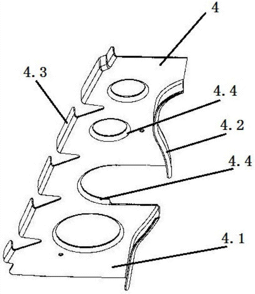
like figure 1 As shown, this part is a partition part, which is used for the connection between aircraft frames and plays the role of partition between different parts of the aircraft. Convex, straight curved-short convex; if there is a problem with one of the convex or convex holes of the part, the operator generally uses the method of manual trimming, but for sheet metal parts with complex structures and small parts , the operating space for workers is very precious, and the mechanism with complex structure takes up a lot of space, coupled with the space occupied by various positioners and product parts, the manual trimming space of parts may not be regular, and the trimming process may not be orderly , manual trimming has the disadvantage of time-consuming and laborious replacement, so designing a device with a convex core that can form the entire complex part becomes a good breakthrough to solve this kind of problem

Method used


Image

  • A forming device and method for small-height convex parts
  • A forming device and method for small-height convex parts
  • A forming device and method for small-height convex parts

Examples


Embodiment Construction

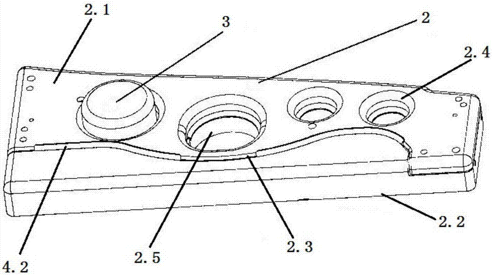
[0023] Such as Figure 2-3 Shown is a forming device for a small height flanged part 4, the part 4 has a main body 4.1, the edge of the main body 4.1 has several arc-shaped flanges 4.2, several straight flanges 4.3, and the main body 4.1 has several Flange hole 4.4, including the first type tire, the second type tire and the core 3;

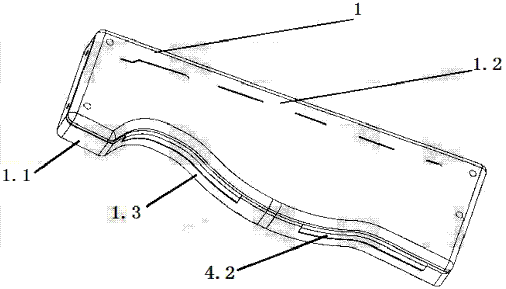
[0024] Such as figure 2 The shape of the first type tire shown matches the shape of the main body 4.1 after the part 4 is formed, that is, the cross section of the first type tire matches the main body 4.1 of the part 4; one side of the first type tire is an arc-shaped surface I1.3, the curvature of the arc-shaped surface I1.3 matches the curvature of the arc-shaped flange on the part 4; the first-type tire is divided into upper and lower parts, which are respectively the first-type tire cover 1.2 and The first type tire carcass 1.1; when forming, the main body 4.1 of the part 4 is located between the first type tire tire cover 1.2 and the fir...


PUM

PropertyMeasurementUnit
heightaaaaaaaaaa

Abstract

The invention discloses a forming device and method suitable for a small-height flanged part. The forming device comprises a first model base, a second model base and a core, wherein the shape of the first model base is matched with the shape of the main body of the formed part; one side surface of the first model base is an arc model surface I, and the curvature of the arc model surface I is matched with that of each arc bending edge of the part; the second model base is provided with a second model base cover and a second model base body; the shape of the second model base cover is matched with the shape of the main body of the part; one side surface of the second model base cover is an arc model surface II, and the curvature of the arc model surface II is matched with that of each arc bending edge of the part; a plurality of through holes I are formed in the second model base cover and matched with flange holes of the part; the second model base body is provided with a plurality of through holes II corresponding to the through holes I; and the outer diameter of the core is matched with the aperture of the flange holes of the part. The forming device has the advantages of being compact in structure, simple, novel and the like, and can meet the extreme and special requirements in production of plane metal sheets. The method is simple, feasible and convenient to operate.

Description

technical field [0001] The invention belongs to the field of forming and processing of aircraft parts, and in particular relates to a forming device and method for small-height convex parts. Background technique [0002] At present, in the design process of aircraft parts, parts with convex edges are gradually increasing, such as convex edges with shorter heights, convex edges with complex shapes, non-standard convex edge holes, etc., and they are densely distributed, which has become a part of today's aircraft. Trends in parts. Such as figure 1 As shown, this part is a partition part, which is used for the connection between aircraft frames and plays the role of partition between different parts of the aircraft. Convex, straight curved-short convex; if there is a problem with one of the convex or convex holes of the part, the operator generally uses the method of manual trimming, but for sheet metal parts with complex structures and small parts , the operating space for ...

Claims


Application Information

Patent Timeline
Patent Type & Authority Patents(China)
IPC IPC(8): B21D53/92B21D37/08B21D35/00
CPCB21D35/001B21D37/08B21D53/92
Inventor 刘娜杜建宇齐红德
Owner SHENYANG AIRCRAFT CORP
Learn More