
Hot air vulcanization equipment

A technology of hot air vulcanization and equipment, applied in the field of vulcanization lines, can solve the problems of damage to plant fiber mattresses and vulcanization equipment, reducing vulcanization efficiency, and waiting for a period of time, so as to shorten the vulcanization time, improve the vulcanization efficiency, and avoid time waste.

Active Publication Date: 2016-10-12
GUIZHOU DAZIRAN TECH
View PDF4 Cites 3 Cited by
  • Summary
  • Abstract
  • Description
  • Claims
  • Application Information

AI Technical Summary

Problems solved by technology

The traditional vulcanization process uses vulcanization equipment such as vulcanization tanks or vulcanization beds, and most of them use microwave vulcanization or far-infrared vulcanization processes. The disadvantages are: plant fiber materials are combustible, and plant fiber materials are easy to burn in a high-temperature and dry environment. Spontaneous combustion occurs, causing damage to plant fiber mattresses and vulcanization equipment. The production risk is high and the cost is high. After curing, you need to wait for a period of time, take it out after vulcanization, and put it into the next batch of plant fiber mattresses to be vulcanized to continue vulcanization, which greatly prolongs the vulcanization time and reduces the vulcanization efficiency

Method used


Image

  • Hot air vulcanization equipment
  • Hot air vulcanization equipment
  • Hot air vulcanization equipment

Examples


Embodiment Construction

[0020] The present invention will be further described below in conjunction with the drawings and embodiments, but it is not a basis for limiting the present invention.

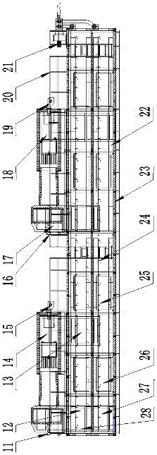
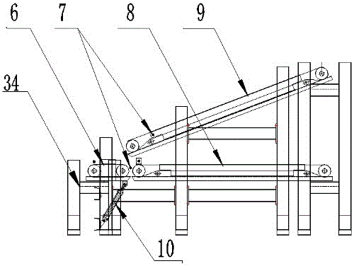
[0021] The embodiment of the present invention: a hot air vulcanization equipment, as attached Figure 1-5 As shown, It includes a vulcanization box 3, which is equipped with a vulcanization conveyor chain. The top of the vulcanization box 3 is provided with a vulcanization line feed inlet combustion chamber 14 at the top of the feed end, and one side of the vulcanization line feed inlet combustion chamber 14 is provided There is a vulcanization line feed inlet burner 15, and the other side is equipped with a vulcanization line feed inlet circulating fan 11, below the vulcanization line feed inlet circulating fan 11 is provided a vulcanization line feed inlet combustion chamber 14 and a vulcanization box 3 The vulcanization line inlet air supply air duct 12, the vulcanization box 3 is provided with a vulcaniza...


PUM

PropertyMeasurementUnit
Angleaaaaaaaaaa

Abstract

The invention discloses hot air vulcanization equipment. The hot air vulcanization equipment comprises a vulcanization tank, and a vulcanization conveying chain is arranged in the vulcanization tank. A vulcanization line feeding inlet combustor and a vulcanization line discharging outlet combustor are arranged on the top of the vulcanization tank. A vulcanization line feeding inlet combustion engine is arranged on one side of the vulcanization line feeding inlet combustor, and a vulcanization line feeding inlet circulating fan is arranged on the other side of the vulcanization line feeding inlet combustor. A vulcanization line feeding inlet air supply channel is arranged below the vulcanization line feeding inlet circulating fan. A vulcanization line air return channel is arranged in the vulcanization tank. A vulcanization line discharging outlet combustion engine is arranged on one side of the vulcanization line discharging outlet combustor, and a vulcanization line discharging outlet circulating fan is arranged on the other side of the vulcanization line discharging outlet combustor. A vulcanization line discharging outlet air supply channel is arranged below the vulcanization line discharging outlet circulating fan. A waste air exhaust fan is arranged in a discharging outlet of the vulcanization tank. The hot air vulcanization equipment has the beneficial effects that the production safety coefficient is high, cost is low, the vulcanization time is short, the vulcanization efficiency is high, and the vulcanization effect is good.

Description

Technical field [0001] The invention involves a vulcanization line, especially a hot air vulcanization equipment. Background technique [0002] The vulcanization line is also called a vulcanized production line. It is an indispensable process step in the production process of plant fiber mattresses. It is mainly to heat the plant fiber mattress after heating through high temperature and change the physical mechanical and chemical properties of its fiber material.The traditional vulcanization process uses vulcanized equipment such as vulcanized tanks or sulfurized beds, and most of them use microwave vulcanization or far -infrared vulcanization process.Self -combustion occurs, causing damage to plant fiber mattresses and sulfide equipment, high production risks, and high costs. At the same time, traditional sulfur beds and sulfur tanks are single sulfur equipment, that is, a batch of plant fiber mattresses put in sulfurization equipment in a batchAfter the middle, you need to wait...

Claims


Application Information

Patent Timeline
IPC IPC(8): B29C35/04B29C31/00
CPCB29C31/008B29C35/002B29C35/045B29C2035/046
Inventor 陈宗勇时小兵廖廷茂徐毅黄龙
Owner GUIZHOU DAZIRAN TECH
Learn More