Transformer
A technology for transformers and installation boxes, applied in the field of transformers, can solve the problems of not being able to put out open fires in time, easy to cause fires, etc.
- Summary
- Abstract
- Description
- Claims
- Application Information
AI Technical Summary
Problems solved by technology
Method used
Image
Examples
Embodiment 1
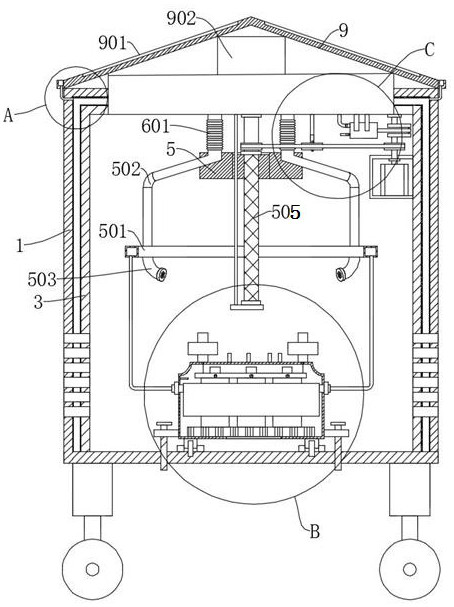
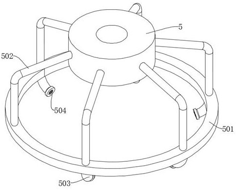
[0030] Embodiment one: refer to Figure 1-7 , a transformer, including an installation box 1, and also includes: an electrical assembly 4 detachably connected to the installation box 1, wherein the electrical assembly 4 includes a housing 401, and a heat sink 402 is arranged in the housing 401, and the heat sink 402 is fixed The winding 403 is connected, and the top of the casing 401 is provided with a terminal 404, which is electrically connected to the winding 403; the shunt box 406 fixedly connected to the inner wall of the casing 401 is used to spray dry powder to the winding 403; it is installed in the installation box 1 Divider ring 501 inside; connection block 5 arranged in installation box 1; second pipeline 502, both ends are connected with connection block 5 and distribution ring 501 respectively; dry powder box 6 fixedly connected on the top of installation box 1; fourth pipeline 601, both ends are respectively connected with the discharge end of the dry powder box ...
Embodiment 2
[0032] Embodiment two: refer to figure 1 and Figure 6 , a transformer, which is basically the same as Embodiment 1, furthermore, the driving part includes a motor 7, the inner shell 3 is fixedly connected in the installation box 1, the motor 7 is fixedly connected to the inner wall of the inner shell 3, and the output end of the motor 7 The drive shaft 701 is fixedly connected, the bottom of the dry powder box 6 is rotatably connected with a reciprocating screw mandrel 505, the connecting block 5 is threaded on the reciprocating screw mandrel 505, and the reciprocating screw mandrel 505 and the drive shaft 701 are rotatably connected through the pulley transmission group 702.
[0033] Start the motor 7, the motor 7 rotates the drive shaft 701, the drive shaft 701 rotates the reciprocating screw mandrel 505 through the pulley transmission group 702, the bottom of the dry powder box 6 is fixedly connected with a guide rod, and the guide rod runs through the connecting block 5, ...
Embodiment 3
[0034] Embodiment three: refer to figure 1 and Figure 6 , a transformer, basically the same as the second embodiment, the pressurized assembly includes a piston 704, the piston 704 is fixedly connected to the bottom of the dry powder box 6, the exhaust end of the piston 704 communicates with the dry powder box 6 through the air pipe 705, and the inlet of the piston 704 The air end communicates with the inside of the installation box 1 , the drive shaft 701 is fixedly connected with a crankshaft 703 , and the drive end of the piston 704 is rotatably connected with the crankshaft 703 .
[0035] The crankshaft 703 makes the piston 704 work, and the input and output ends of the piston 704 are provided with check valves. The piston 704 absorbs the air inside the installation box 1 and sends it into the dry powder box 6, increasing the pressure in the dry powder box 6, and using the pressure to make the dry powder The dry powder box 6 is ejected to spray the dry powder onto the co...
PUM
 Abstract
Description
Claims
Application Information
 - R&D
- Intellectual Property
- Life Sciences
- Materials
- Tech Scout
- Unparalleled Data Quality
- Higher Quality Content
- 60% Fewer Hallucinations
Browse by: Latest US Patents, China's latest patents, Technical Efficacy Thesaurus, Application Domain, Technology Topic, Popular Technical Reports.
© 2025 PatSnap. All rights reserved.Legal|Privacy policy|Modern Slavery Act Transparency Statement|Sitemap|About US| Contact US: help@patsnap.com


