Application of self-repair material in 3D printing

A self-healing material and 3D printing technology, applied in the field of 3D printing, can solve problems affecting product life, waste, and functional impact, and achieve the effects of increasing service life, improving utilization, and reducing maintenance costs

Active Publication Date: 2016-10-12
NANJING UNIV
View PDF3 Cites 18 Cited by
  • Summary
  • Abstract
  • Description
  • Claims
  • Application Information

AI Technical Summary

Problems solved by technology

[0003] 3D printing technology has made impressive progress, but some challenges remain
The products prepared by 3D printing materials are integrally formed at one time, and the functionality of the entire product will be affected after microcracks or damage from the outside world, so we can only choose to replace them. In...

Method used


Image

  • Application of self-repair material in 3D printing
  • Application of self-repair material in 3D printing
  • Application of self-repair material in 3D printing

Examples


Embodiment 1

[0139] (1) Calculated according to the mass fraction, take 50 parts of polysiloxane A, dissolve in 50 parts of dichloromethane, take 50 parts of polysiloxane B, dissolve in 50 parts of dichloromethane, and dissolve the polysiloxane at 25 °C Mix the solutions of siloxane A and polysiloxane B, and stir for 2 hours at 25°C under mechanical stirring at 1000rmp / min to obtain the pre-printed material;

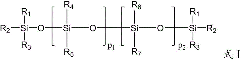
[0140] The structural formula of polysiloxane is shown in formula I,

[0141] Among them, R 1 ~R 6 is methyl;

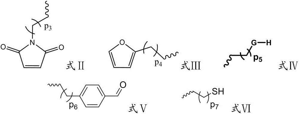
[0142] Polysiloxane A, R 7 is formula Ⅱ, where, p 1 equal to p 2 , is a value between 80 and 100, p 3 The value of is 1;

[0143] Polysiloxane B, R 7 is formula Ⅲ, among them, p 1 equal to p 2 , is a value between 80 and 100, p 4 The value of is 1;

[0144] (2) Heat the pre-printed material obtained in (1) in an oil bath at a rate of 10°C / min, raise the temperature to 75°C, and react for 12h under mechanical stirring at 1000rmp / min; the reaction is over Finally...

Embodiment 2

[0148] (1) Calculated according to the mass fraction, take 50 parts of polysiloxane A, dissolve in 50 parts of dichloromethane, take 50 parts of polysiloxane B, dissolve in 50 parts of dichloromethane, and dissolve the polysiloxane at 25 °C Mix the solutions of siloxane A and polysiloxane B, and stir for 2 hours at 25°C under mechanical stirring at 1000rmp / min to obtain the pre-printed material;

[0149] The structural formula of polysiloxane is shown in formula I,

[0150] Among them, R 2 ~R 7 is methyl;

[0151] Polysiloxane A, R 1 is formula Ⅳ, among them, p 1 equal to p 2 , is a value between 80 and 100, p 5 The value of is 3, G is -NH-;

[0152] Polysiloxane B, R 1 is formula Ⅴ, among them, p 1 equal to p 2 , is a value between 80 and 100, p 6 The value of is 1;

[0153] (2) Heat the pre-printed material obtained in (1) in an oil bath at a rate of 10°C / min, raise the temperature to 75°C, and react for 6 hours under mechanical stirring at 1000rmp / min; Heating ...

Embodiment 3

[0157] (1) Calculated according to the mass fraction, take 50 parts of polysiloxane A, dissolve in 50 parts of tetrahydrofuran, take 50 parts of polysiloxane B, dissolve in 50 parts of tetrahydrofuran, and dissolve polysiloxane A at 25°C Mix with the solution of polysiloxane B, and stir for 2 hours at 25°C under mechanical stirring at 1000rmp / min. get pre-printed material;

[0158] The structural formula of polysiloxane is shown in formula I,

[0159] Polysiloxane A, R2 ~R 7 is methyl, R 1 is the formula Ⅵ, p 7 is 3, p 1 equal to p 2 , is a value between 80 and 100;

[0160] Polysiloxane B, R 1 ~R 6 is methyl, R 7 is the formula Ⅵ, p 7 is 3, p 1 equal to p 2 , is a value between 80 and 100;

[0161] (2) To the preprinted material obtained in (1), add 100 parts of H 2 o 2 , at 25°C, reacted for 6h under mechanical stirring at 1000rmp / min. Then heat at a rate of 10°C / min, raise the temperature to 50°C, and react for 6h under mechanical stirring at 1000rmp / min; 0...


PUM


Abstract

The invention provides application of a self-repair material in 3D printing. The self-repair material is taken as a 3D printing material, the self-repair function of the self-repair material is utilized, and the material is intelligently detected and is spontaneously repaired, so that potential damage of the self-repair material caused by generated micro-cracks can be prevented; compared with molding conditions of a product, self-repair needs the light and mild conditions, from the beginning to finishing of the self-repair, the whole performance of the product cannot be affected, the maintenance cost for the product is decreased, the service life of the product is prolonged, and the resource utilization rate is increased.

Description

technical field [0001] The invention relates to the technical field of 3D printing, in particular to the application of self-repairing materials in 3D printing. Background technique [0002] 3D printing technology (3D Printing) is a rapidly developing emerging technology in the field of manufacturing in this century, known as "manufacturing technology with industrial revolution significance". This technology is a type of rapid prototyping technology, also known as additive manufacturing. The basic principle of 3D printing technology is similar to that of inkjet printing technology or laser printing technology. Based on the digital model file, the 3D model prepared by design or scanning is cut into infinite sections according to a certain coordinate axis, and then the The corresponding materials are printed layer by layer from the printer nozzle, shaped by cooling or light curing, or selectively sintered or melted by laser, and piled together according to the original positi...

Claims


Application Information

Patent Timeline
IPC IPC(8): C08L83/08C08L83/06B33Y70/00
CPCB33Y70/00C08L83/06C08L83/08C08L2205/025
Inventor 李承辉赖建诚游效曾
Owner NANJING UNIV
Why Eureka
Try Eureka