
A large-stroke frictionless spindle of a braiding machine

A frictionless, large-stroke technology, applied in the direction of braided fabrics, textiles, and papermaking, can solve the problems of easy breakage of fine yarns, short strokes of thread falling, and easy wear of yarn surfaces, so as to reduce wear and increase pay-off Stroke, increased stability effect

Active Publication Date: 2017-10-10
XUZHOU HENGHUI BRAIDING MACHINE
View PDF5 Cites 0 Cited by
  • Summary
  • Abstract
  • Description
  • Claims
  • Application Information

AI Technical Summary

Problems solved by technology

[0004] The purpose of the present invention is to provide a large-stroke frictionless spindle of a knitting machine, which solves the problem of large friction of the existing spindle, easy wear and tear on the surface of the yarn, labor-intensive unwinding, and short stroke of the thread drop, making it uneven in weaving and fine yarns. breakable problem

Method used


Image

  • A large-stroke frictionless spindle of a braiding machine
  • A large-stroke frictionless spindle of a braiding machine
  • A large-stroke frictionless spindle of a braiding machine

Examples


Embodiment 1

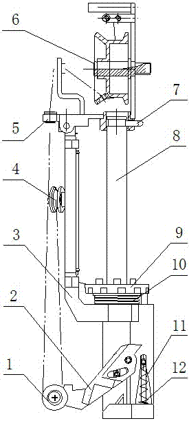
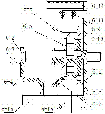
[0027] Embodiment 1: The spindle includes: the lower thread wheel 1, the thread pendant 2, the spindle rod 3, the upper thread wheel 4, the threading sleeve 5, the take-up and take-off device 6, the circlip 7, the bobbin shaft 8, the face plate 9, Tensioner 10, top pin 11 and compression spring 12; a wire dropper 3 is connected to the lower part of the spindle bar 3, a top pin 11 and a clip spring 12 are connected to the spindle bar 3 at one end of the line dropper 3, and the other end of the line dropper 3 is connected There is a lower wire wheel 1; there is a faceplate 9 in the middle of the spindle bar 3, and a bobbin shaft 8 is arranged in the center of the faceplate 9, and the bobbin shaft 8 is connected with the spindle bar as a whole, and a tensioner is connected between the faceplate 9 and the spindle bar 10. The tensioner 10 is synchronized with the pay-off to prevent loosening of the pay-off; the upper wire pulley 4 is connected to the middle part of one side of the s...


PUM


Abstract

The invention provides a large-stroke friction-free spindle mechanism of a braider, belonging to spindle mechanisms of braiders. The spindle comprises a lower yarn passing wheel, a plummet, a spindle blade, an upper yarn passing wheel, a threading sleeve, a take-up and pay-off device, a clamp spring, a bobbin shaft, a faceplate, a tensioner, a lifting pin and a pressure spring, wherein the plummet is connected below the spindle blade; the lifting pin and the pressure spring are connected to the spindle blade at one end of the plummet; the lower yarn passing wheel is connected at the other end of the plummet; the faceplate is arranged in the middle of the spindle blade; the bobbin shaft is arranged in the center of the faceplate and is connected with the spindle blade into a whole; the tensioner is connected between the faceplate and the spindle blade; the upper yarn passing wheel is connected in the middle of one side of the spindle blade; the threading sleeve is connected above one side of the spindle blade; one end of the take-up and pay-off device is connected to the bobbin shaft by the clamp spring and the other end of the take-up and pay-off device is hinged with the top end of the spindle blade. The spindle has the advantages that the pay-off stroke of the spindle is increased by adopting the rolling and take-up modes, so the spindle is suitable for two-dimensional and three-dimensional guide rail braiders; yarn surfaces are friction-free and yarn material surfaces are not damaged, thus increasing the product quality and yield.

Description

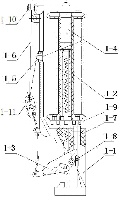
technical field [0001] The invention relates to a spindle of a braiding machine, in particular to a large-stroke frictionless spindle of a braiding machine. Background technique [0002] The high-speed machine spindles generally used on braiding machines, such as figure 1 As shown, including: spindle rod (1-1), bobbin (1-2), thread pendant (1-3), bobbin shaft (1-4), porcelain eye (1-5), brake cutting shaft ( 1-7), brake cutting shaft horizontal pin (1-8), face plate (1-9), outlet hole (1-10) and wire pendant porcelain eye (1-11); There is bobbin shaft (1-4), bobbin (1-2) is sleeved on bobbin shaft (1-4), thread pendant (1-3) is stuck on both sides of spindle bar (1-1), thread pendant (1-3) One end is provided with thread drop porcelain eyes (1-11), and the spindle bar (1-1) is provided with porcelain eyes (1-5). When working, the yarn (1-6) passes through the spindle bar porcelain eyes ( 1-5), and then bent to the outlet hole (1-10) through the thread drop porcelain eye (...

Claims


Application Information

Patent Timeline
Patent Type & Authority Patents(China)
IPC IPC(8): D04C3/00
CPCD04C3/00
Inventor 韩百峰许福军
Owner XUZHOU HENGHUI BRAIDING MACHINE
Learn More