Suspension self-excitation runner piezoelectric beam energy harvester

A technology of piezoelectric beams and energy harvesters, applied in piezoelectric effect/electrostrictive or magnetostrictive motors, electrical components, machines/engines, etc., can solve problems such as limited service life, power supply, and inability to pass cables , to achieve the effect of effective frequency bandwidth, large power generation and high reliability

Active Publication Date: 2016-10-12
ZHEJIANG NORMAL UNIVERSITY
View PDF5 Cites 10 Cited by
  • Summary
  • Abstract
  • Description
  • Claims
  • Application Information

AI Technical Summary

Problems solved by technology

[0003] For the monitoring of gears and shafts, the ideal method is to install various sensor monitoring systems on or close to the gears or shafts, so as to realize direct online monitoring of their operating status; It is difficult to popularize and apply the reliable and sufficient power supply for the sensor monitoring system because: ① gears and shafts are in a state of rotating motion and cannot be powered by cables; ② if battery power is used, the battery needs to be replaced frequently due to its limited serv...

Method used


Image

  • Suspension self-excitation runner piezoelectric beam energy harvester
  • Suspension self-excitation runner piezoelectric beam energy harvester
  • Suspension self-excitation runner piezoelectric beam energy harvester

Examples


Embodiment Construction

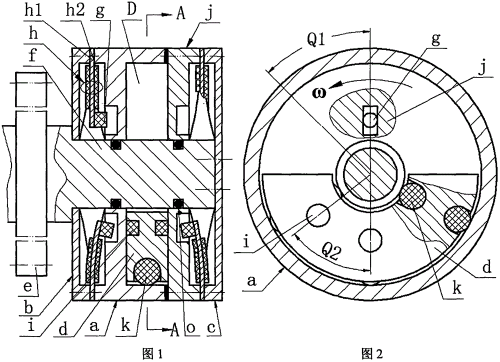
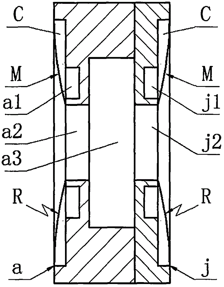
[0016] The left end cover b, disc body a, side plate j and right end cover c are sequentially connected by screws, the left end cover b, disc body a and side plate j are set on the cantilever shaft f of gear e, and the right end cover c is connected to the cantilever shaft by screws f connection; there is a sealing ring o between the cantilever shaft f and the central hole a2 of the plate a and the central hole j2 of the side plate j; between the left end cover b and the plate a and between the side plate j and the right end cover c The metal substrate h1 is crimped, and the cantilever beam h11 on the metal substrate h1 and the bonded piezoelectric chip h2 form a piezoelectric vibrator h; the free end of the piezoelectric vibrator h is installed with an excited magnet g through screws, and the excited magnet g It is installed close to the disk a or the side plate j and placed in the rectangular guide groove a1 on the side of the disk a or in the rectangular guide groove j1 on t...


PUM


Abstract

The invention relates to a suspension self-excitation runner piezoelectric beam energy harvester and belongs to the field of piezoelectric power generation. A left end cap, a disc body, a side plate and a right end cap are sequentially connected and are arranged on a cantilevered shaft in a sleeving mode. A cantilever beam of a metal substrate and a bonded piezoelectric crystal plate between the left end cap and the disc body form a piezoelectric vibrator, and a cantilever beam of a metal substrate and a bonded piezoelectric crystal plate between the side plate and the right end cap form a piezoelectric vibrator. The piezoelectric vibrators are provided with excited magnetics. An exciter is mounted in a slideway form by the cantilevered shaft and an annular cavity of the disc body. Balls are embedded in the inner edge and the outer edge of the exciter, and exciting magnets are embedded in the two sides of the exciter. The piezoelectric vibrators on the two sides of the exciter are equal in number and are symmetrically mounted. The side of the left end cap, the side of the disc body, the side of the side plate and the side of the right end cap which are adjacent to the piezoelectric vibrators are provided with limiting faces and sink grooves which are identical in shape, size and number. The suspension self-excitation runner piezoelectric beam energy harvester has the advantages and characteristics that fixing and supporting are not needed, structure is simple, and rotation force to the exciter is small; the piezoelectric vibrators are reasonable in structure and equal in stress of points after deformation, the power generation amount is large, the reliability is high, and effective frequency band is wide; and the suspension self-excitation runner piezoelectric beam energy harvester can be used as a standardized part to be applied to cantilevered shaft gears and the multi-gear coaxial occasions.

Description

technical field [0001] The invention belongs to the technical field of new energy and power generation, and in particular relates to a piezoelectric beam energy harvester of a suspended self-excited runner, which is used for power supply of a health monitoring system that is inconvenient to install a relatively fixed support rotating structure such as a wind power generator gear shaft. Background technique [0002] The gearbox is a key component of a wind turbine, and its function is to transmit power. When the wind turbine is running normally, the speed of the wind rotor is low, resulting in low efficiency of the generator. Therefore, it is necessary to increase the power generation capacity and efficiency through the gearbox. Because the wind power gearbox works in a variable speed and variable load environment, it is prone to failure; in addition, when the wind power gearbox fails, it is difficult to repair and the cost is high. The operation and maintenance cost of the w...

Claims


Application Information

Patent Timeline
IPC IPC(8): F03G3/00H02N2/18
CPCF03G3/00H02N2/18
Inventor 张忠华文欢程光明阚君武王淑云
Owner ZHEJIANG NORMAL UNIVERSITY
Why Eureka
Try Eureka