Supercharge Your Innovation With Domain-Expert AI Agents!

Work method for hydraulic heat exchange system with impact-resistance energy accumulation radiator

A technology of heat exchange system and working method, which is applied in the field of hydraulic heat exchange system, can solve the problems of increased pressure, unbalanced flow, easily damaged radiator, and scrapped, etc., and achieves the effect of not easy to be damaged and high reliability

Inactive Publication Date: 2016-10-12
江苏金荣森制冷科技有限公司
View PDF3 Cites 0 Cited by
  • Summary
  • Abstract
  • Description
  • Claims
  • Application Information

AI Technical Summary

Problems solved by technology

It has a small liquid storage capacity and no buffer. In the case of large temperature difference, low temperature environment, unbalanced flow, liquid with a certain viscosity, and fluid with impact force, the pressure inside the heat dissipation channel of the radiator will also increase. , especially in the case of impact force and relatively high viscosity fluid, due to the resistance of the fluid inside the channel, the fluid cannot quickly pass through the inside of the radiator channel, so that the pressure increases, exceeding the maximum operating pressure of the radiator, and the radiator is very Easily damaged and scrapped

Method used


Image

  • Work method for hydraulic heat exchange system with impact-resistance energy accumulation radiator
  • Work method for hydraulic heat exchange system with impact-resistance energy accumulation radiator
  • Work method for hydraulic heat exchange system with impact-resistance energy accumulation radiator

Examples


Embodiment 1

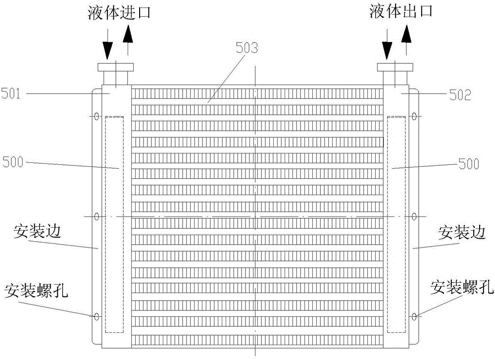
[0046] The accumulator tube is built in. When the liquid inlet and outlet of the anti-impact energy storage radiator are located on the top of the first liquid collection tank 501 and the second liquid collection tank 502, the energy storage tube 500 is installed in the first liquid collection tank 501 and the second liquid collection tank 502. The inside of the second liquid collection tank 502 is enough.

Embodiment 2

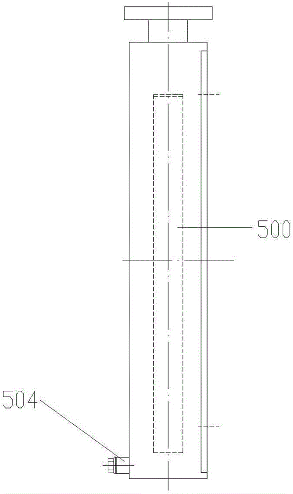
[0048] The accumulator tube is built in, and when the liquid inlet and outlet of the anti-impact energy storage radiator are located on the sides of the first liquid collection tank 501 and the second liquid collection tank 502, the energy storage tube 500 is installed on the first liquid collection tank 501 and the second liquid collection tank 502. Inside the second liquid collecting tank 502, if the height of the accumulator tube 500 is higher than the height of the liquid inlet and the liquid outlet, no other treatment is required; if the height of the accumulator tube 500 is lower than the height of the liquid inlet and the liquid outlet , it is necessary to install a diverter baffle 507 on the top of the energy storage tube 500, the diverter baffle 507 separates the liquid inlet and outlet from the diverter liquid tank 503 at the corresponding height, so as to avoid the direct impact of the liquid into the diverter liquid tank 503 .

Embodiment 3

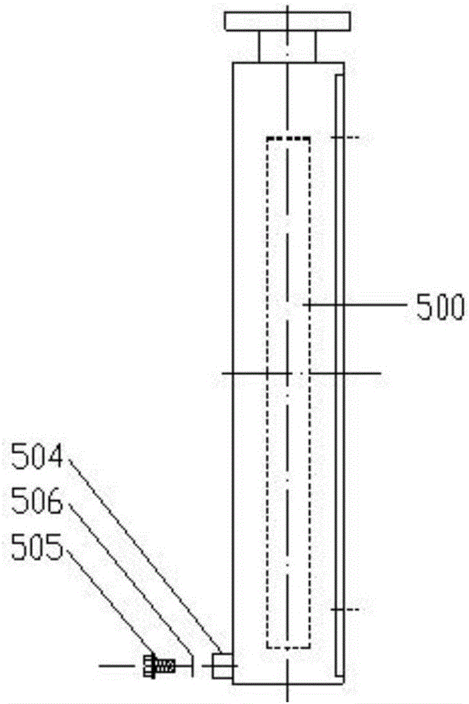
[0050] The energy storage tube is placed outside, and the liquid inlet and liquid outlet of the anti-impact energy storage radiator are located at the top of the first liquid collection tank 501 and the second liquid collection tank 502 . The opening at the bottom of the accumulator tube 500 is threadedly connected to the connection ports on the bottom side of the first sump 501 and the second sump 502, and the top of the accumulator tube 500 is connected to the first sump 501 and the second sump. The mounting edge on the top side of the liquid tank 502 is fixedly connected by bolts, which is convenient for disassembly and assembly. Because the energy storage tube 500 of the anti-shock energy storage radiator is arranged outside the first liquid collection tank 501 and the second liquid collection tank 502, it is possible to select different capacity and various energy storage tubes according to the difference in liquid flow and impact force. .


PUM


Abstract

The invention relates to a work method for a hydraulic heat exchange system with an impact-resistance energy accumulation radiator. The work method is characterized in that the hydraulic heat exchange system with the impact-resistance energy accumulation radiator comprises an equipment heating source, a radiator and a liquid storage box of which oil ways are connected cyclically in series; a radiating draught fan is arranged on one side of the radiator which is the impact-resistance energy accumulation radiator; the radiator comprises a radiator body and an energy accumulation pipe; the radiator body comprises a first liquid collecting groove and a second liquid collecting groove which are vertically arranged in the left-right direction; multiple branch liquid flowing grooves which are transversely arranged are connected between the first liquid collecting groove and the second liquid collecting groove; the energy accumulation pipe is of a pipe type structure with the bottom opened and the rest part closed; and an opening in the bottom of the energy accumulation pipe communicates with the first liquid collecting groove and the second liquid collecting groove. The work method has the beneficial effects that reliability is high, damage is not likely to happen, and the stable running of the system is ensured.

Description

technical field [0001] The invention relates to a working method of a hydraulic heat exchange system with an anti-shock energy storage radiator. Background technique [0002] As we all know, the best oil temperature of the hydraulic system is between 35 and 55 degrees Celsius. Once the temperature rises above 60 degrees Celsius, the system of the hydraulic system will drop significantly, and equipment failures will continue to occur, resulting in a serious decline in the stability of the equipment. The proper functioning of the machine equipment cannot be guaranteed. Especially in the midsummer season, the oil temperature is too high, and even the machinery and equipment are often shut down. [0003] Therefore, the stability of the hydraulic heat exchange system directly affects the working status of the machinery and equipment. When the liquid pressure in the traditional hydraulic heat exchange system is too high, it will directly lead to excessive pressure in the heat exc...

Claims


Application Information

Patent Timeline
IPC IPC(8): F28D20/00F28F27/00F28D1/06
CPCF28D1/06F28D20/0034F28D2020/0069F28D2020/0078F28F27/00F28F2265/00Y02E60/14
Inventor 黄晓军
Owner 江苏金荣森制冷科技有限公司
Features
  • R&D
  • Intellectual Property
  • Life Sciences
  • Materials
  • Tech Scout
  • Unparalleled Data Quality
  • Higher Quality Content
  • 60% Fewer Hallucinations
Learn More