
A Single Magnetic Core Complicated Waveform Current Sensor

A technology of current sensor and single magnetic core, which is applied in the direction of only measuring current, measuring current/voltage, instruments, etc. It can solve the problems of increasing the volume of the current sensor, complicating the structure, and increasing the cost, so as to expand the measurement range and frequency and reduce the volume , the effect of improving the accuracy

Inactive Publication Date: 2018-09-18
HEBEI UNIV OF TECH
View PDF10 Cites 0 Cited by
  • Summary
  • Abstract
  • Description
  • Claims
  • Application Information

AI Technical Summary

Problems solved by technology

However, the disadvantages of this sensor are: due to the introduction of the third ring, the volume of the current sensor is increased, and the cost is increased; the ring core is wound around the secondary winding, the feedback winding, and the structure is complex
The document "High-Bandwidth High-Temperature (250℃ / 500F) Isolated DC and AC CurrentMeasurement: Bidirectionally Saturated Current Transformer" proposes a measurement method based on the principle of fluxgate, that is, the principle of bidirectional saturated fluxgate. This measurement method Accurate measurement of medium and low frequency currents in high temperature environments can be achieved, but complex current waveform measurements are difficult to achieve with this method

Method used


Image

  • A Single Magnetic Core Complicated Waveform Current Sensor
  • A Single Magnetic Core Complicated Waveform Current Sensor
  • A Single Magnetic Core Complicated Waveform Current Sensor

Examples


Embodiment 1

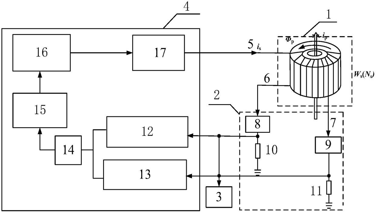
[0057] The composition of a single magnetic core complex waveform current sensor in this embodiment is as follows: figure 1 As shown, the number of turns of the primary coil of the current probe 1 is 1 turn, and the number of turns of the secondary coil is 50 turns. The material used for the magnetic core of the current probe 1 is an ultrafine crystal soft magnetic material, and its saturation magnetic flux density is B s =1.2T, coercive force H c -8 ~10 -6 , the magnetic permeability is 30000-80000H / m, the inner diameter of the ring magnetic core is 5.1mm, the outer diameter is 11.2mm and the height is 5.8mm. The material used for the winding is enameled wire with a diameter of 0.38mm.


PUM


Abstract

The invention discloses a single magnetic core complex waveform current sensor including a current probe, a signal processing circuit, an analog-to-digital conversion circuit and a feedback control circuit. The current probe comprises an excitation current incoming end, a low frequency excitation current outgoing end and a high frequency excitation current outgoing end. The signal processing circuit includes a low-pass filter, a high-pass filter, a first sampling resistor and a second sampling resistor. The feedback control circuit comprises a single limit voltage comparator, a double limit voltage comparator, an OR gate circuit, a D flip-flop, a MOSFET drive circuit and an H bridge inverter circuit. The sensor utilizes the signal processing circuit and the feedback control circuit and can effectively measure high-frequency complex current waveform. The signal processing circuit separates the high frequency current and the low frequency current and uses different principles for measurement of the currents, then the feedback control circuit measures the high and low frequency currents at the same time, so that magnetic saturation of a magnetic core of the current probe is effectively improved, and the accuracy of high frequency current component measurement is improved.

Description

technical field [0001] The invention relates to a device for measuring current, in particular to a single magnetic core complex waveform current sensor. Background technique [0002] Power electronics technology and its practical application requirements are mutually reinforcing and have developed rapidly. Emerging markets such as smart grids, renewable energy, and electric vehicles have further promoted the development of power electronics technology. Modern power electronics technology takes high frequency as its development direction and has many advantages; but one of the problems that follow is the increase in the difficulty of current detection. There are often complex current waveforms in high-frequency and high-power power electronic equipment, including DC, low-frequency AC, and high-frequency components up to tens of kilohertz; at the same time, high-frequency power electronic devices often operate in high-temperature environments. Accurate detection of complex c...

Claims


Application Information

Patent Timeline
Patent Type & Authority Patents(China)
IPC IPC(8): G01R19/00
CPCG01R19/0092
Inventor 杨晓光郑伟东朱波
Owner HEBEI UNIV OF TECH
Learn More