
Sparse array digital wave beam formation method based on data reconstruction

A digital beam and data reconstruction technology, applied in radio wave measurement systems, instruments, etc., can solve the problem of difficulty in ensuring beam performance, and achieve the effect of zero depression in the interference direction, convenient system implementation, and close performance.

Active Publication Date: 2016-10-12
NANJING UNIV OF SCI & TECH
View PDF5 Cites 14 Cited by
  • Summary
  • Abstract
  • Description
  • Claims
  • Application Information

AI Technical Summary

Problems solved by technology

When the beam is scanning or performing adaptive interference suppression, the same array structure is difficult to guarantee the performance of the beam, so an optimized array arrangement method is sought, so that the designed sparse array can form a variety of shapes of the pattern, which can be automatically Adapt to interference suppression, so that the designed array structure can ensure the performance of the beam during adaptive interference suppression as much as possible, and reduce the number of array elements as much as possible

Method used


Image

  • Sparse array digital wave beam formation method based on data reconstruction
  • Sparse array digital wave beam formation method based on data reconstruction
  • Sparse array digital wave beam formation method based on data reconstruction

Examples


Embodiment Construction

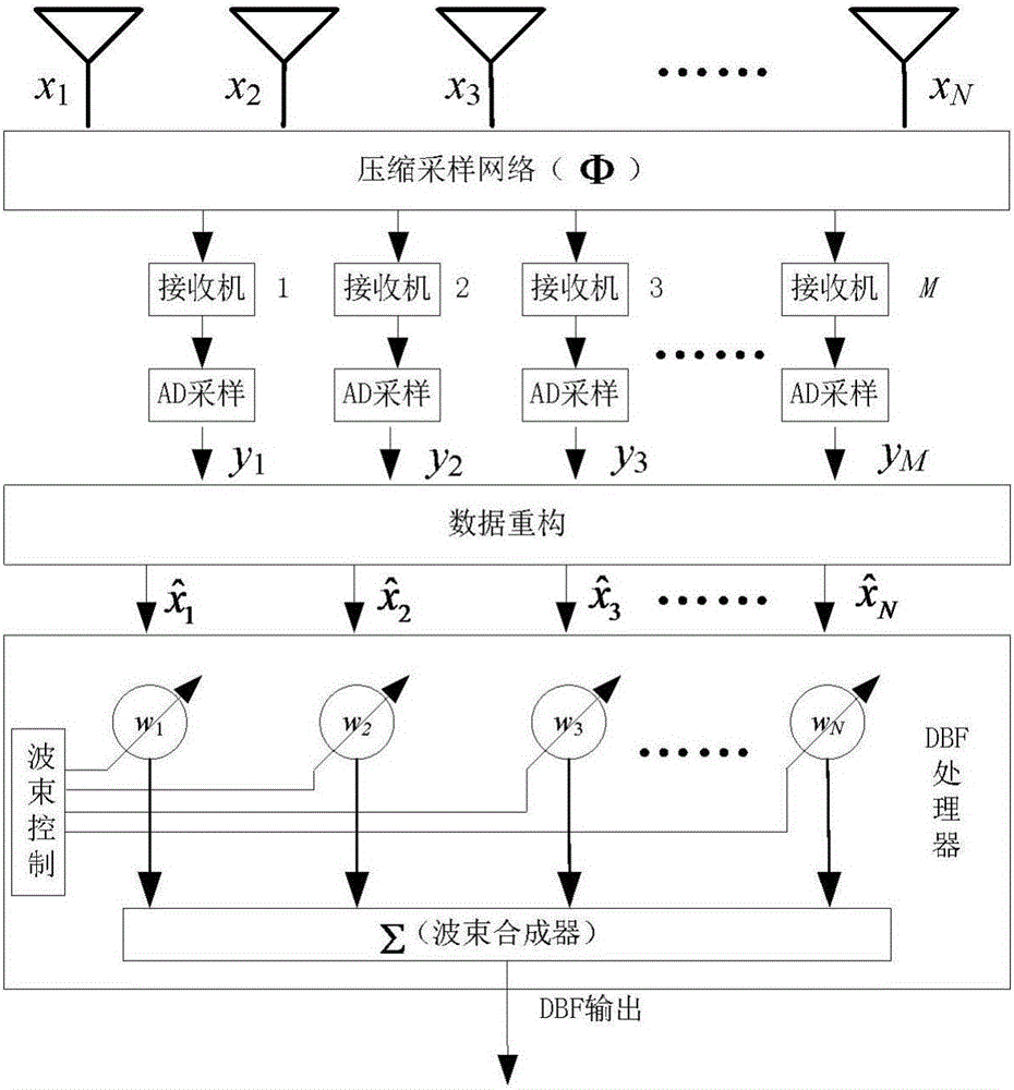
[0024] Implementation steps of the present invention are as figure 1 As shown, two modules are added to the traditional DBF radar antenna system: compressed sampling network and data reconstruction module. The operation steps of this method are described in detail below.

[0025] Consider a full-array linear array antenna, with N array elements evenly arranged, and the array element spacing is ( / 2((for the radar’s working wavelength). There are K far-field echo signals incident on the antenna array. One of them is a desired signal, and the remaining K-1 are interference signals. The received signal of each array element of the array antenna is represented by a vector X (t) of N dimensions, and X (t)=[x 1 (t),x 2 (t),...,x N (t)] T . Regardless of the receiver noise first, there is

[0026] X ( t ) = Σ k = 1 K ...


PUM


Abstract

The invention provides a sparse array digital wave beam formation method based on data reconstruction. The method comprises the following steps that 1) the amount of antennas and the amount of RF channels of a system array are determined; 2) according to an array structure, a compressing and sampling network matrix is designed, signals received by different array elements of the array antennas are projected to the network matrix for compression and sampling, and compression and sampling data is obtained; 3) down conversion and A / D sampling are carried out on RF data obtained by compressing and sampling, and baseband digital signals are obtained; 4) a self-adaptive grid adjustment based reconstruction algorithm is used for recovery to obtain echo signals of different channels during full array; and 5) the data obtained by reconstruction is used to for digital wave beam formation, wave beams are formed, and expected direction signals are obtained. The method can be used to greatly reduce the amount of RF channels as well as the cost of radar array antennas, and a formed directional diagram has the advantages of low sidelobe, accurate direction, zero recess depth in the interference direction and the like.

Description

technical field [0001] The invention relates to an array signal processing technology, in particular to a sparse array digital beamforming method based on data reconstruction. Background technique [0002] An array antenna is a special antenna that is arranged regularly or randomly by no less than two antenna elements and obtains predetermined radiation characteristics through proper excitation. The array antenna beam has the characteristics of strong directivity, low side lobe, and easy electronic scanning, etc., and has been widely used in radar and communication electronic systems. Digital beamforming technology is one of the current research hotspots. By adding different weight coefficients, different array patterns can be formed, so that the main lobe points to the desired direction, and its null traps are aligned with the interference direction, improving the array as much as possible. Output the strength of the desired signal while reducing the strength of the interf...

Claims


Application Information

Patent Timeline
IPC IPC(8): G01S7/02
CPCG01S7/02
Inventor 韩玉兵王建盛卫星蒋跃李曙光施云飞
Owner NANJING UNIV OF SCI & TECH
Learn More