Projection screen, large-size spliced screen and projection system

A projection screen and projection technology, applied in optics, instruments, projection devices, etc., can solve the problems of inconsistent color of images and reduce user experience, and achieve the effect of improving consistency, improving user experience, and reducing color cast.

Active Publication Date: 2016-10-12
HISENSE
View PDF7 Cites 10 Cited by
  • Summary
  • Abstract
  • Description
  • Claims
  • Application Information

AI Technical Summary

Problems solved by technology

[0004] The direct visual manifestation of color shift is that the white point is no longer the preset color temperature value, but biased towards a certain primary color display, so that the human eye has inconsistencies in the image color when viewing the display screen from different angles of view or different positions, especially for In the large-screen splicing display, for scenes that use a lot of white space, such as PPT display in large conference rooms, the color cast of different viewing angles or different positions will greatly reduce the user experience

Method used


Image

  • Projection screen, large-size spliced screen and projection system
  • Projection screen, large-size spliced screen and projection system
  • Projection screen, large-size spliced screen and projection system

Examples


Embodiment 1

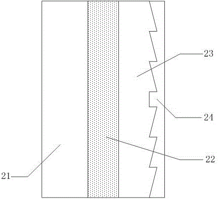
[0044] Such as Figure 2A Shown is a schematic structural view of a front projection screen in the prior art, including: a colored layer 21, a diffusion layer 22, a Fresnel lens layer 23 and a reflective layer 24, wherein the colored layer 21 is located on the outermost side of the projection screen, The projected image beam first enters and finally exits through this layer. The main function of the coloring layer is to improve the color reproduction ability of the projection screen. Sometimes the coloring layer 21 can also be replaced by a substrate layer. The substrate layer includes a coloring layer and a hard film layer. , the hard film layer mainly plays a protective role.

[0045] The diffusion layer 22 is mainly used to homogenize the uneven incident light and expand the angle of the outgoing light.

[0046] The Fresnel lens layer 23 is used for collimating and parallelizing the incident light beams within a certain angle range, and diverging the light beams reflected ...

Embodiment 2

[0070] Such as Figure 2C As shown, a schematic structural diagram of a rear projection screen in the prior art, the projection direction of the lens is consistent with the outgoing direction of the screen image beam. As shown in the figure, along the projected image light beam exit direction, it passes through the Fresnel lens structure layer 11 and the lenticular lens structure layer 12 successively. screen. The specific light path diagram is as Figure 2D As shown, the Fresnel lens structure layer 11 converges and collimates the light incident on the screen, and the convex lens part in the lenticular lens structure layer 12 receives the collimated light and converges it. Theoretically, imaging is performed on the focal plane of the convex lens, and Finally, the transmission is conducted from the lenticular lens structure layer 12 in a convergent and then divergent state.

[0071] To improve the above-mentioned existing rear projection screen, another projection screen pr...

Embodiment 3

[0093] Embodiment 3 of the present invention is based on Embodiment 1, and proposes a large-size spliced ​​projection screen, such as Figure 5 shown.

[0094] Figure 5 The large-sized splicing screen shown can be applied to the front-projection projection screen in Embodiment 1, that is, the projection device and the user are located on one side of the projection screen, and what the user observes is the image formed by the reflection of the screen into the human eye.

[0095] or, Figure 5 The large-size splicing screen shown can be applied to the rear-projection projection screen in Embodiment 1, that is, the projection device and the user are located on both sides of the projection screen, and what the user observes is the image formed by the screen and transmitted into the human eye.

[0096] Since the large-size splicing screen applies the projection screen technical solution described in Embodiment 1 or Embodiment 2, it can reduce the color unevenness and color shift...


PUM


Abstract

The invention discloses a projection screen which comprises a Fresnel lens layer and a micro lens layer located on the light-out side of the Fresnel lens layer. The micro lens layer comprises a plurality of micro lens sets distributed in an array. Each micro lens set sequentially comprises a first micro lens which is a concave lens and a second micro lens which is a convex lens in the projection image light beam emitting direction, wherein the dispersion coefficient of the first micro lens is smaller than that of the second micro lens. Projection image light beams at least pass through the Fresnel lens layer, are finally emitted through the micro lens layer and enter human eyes. According to the technical scheme, two kinds of lenses different in dispersion coefficient are arranged, the rear lenses can compensate for deflection difference of light beams transmitted by the front lenses, the coincidence degree of primary light beams is improved, and the color error phenomenon caused when images are watched on the projection screen at different view angles is eliminated.

Description

technical field [0001] The invention relates to the field of display technology, in particular to a projection screen, a splicing screen and a projection system. Background technique [0002] In the field of projection display, especially in the field of projection display, the use of projection screens has gradually developed from the traditional white screen to the use of hard screens. At present, the commonly used optical screens are hard screens, such as Fresnel screens, Fresnel screens Using the principle of Fresnel lens structure, the light beam incident at a certain angle can be collimated into parallel light, and finally sent to the human eye for imaging, which can reduce the interference of ambient light and improve the brightness and contrast of the screen. [0003] However, in practical applications, according to the test results of the white field of the image emitted by the projection screen, the technicians found that the color shift at the center of the screen...

Claims


Application Information

Patent Timeline
Patent Type & Authority Applications(China)
IPC IPC(8): G03B21/625
CPCG03B21/625
Inventor 赵飞
Owner HISENSE
Why Eureka
Try Eureka