

DOA estimation method in co-prime array based on iteration sparse reconstruction
A sparse reconstruction and DOA technology, applied in the field of DOA estimation based on iterative sparse reconstruction, can solve the problems of undetectable transmission power, difficulty in estimating performance, and affecting the effect of reconstruction, etc., to achieve low transmission power and improve estimation Accuracy and resolution, the effect of increasing the degree of freedom
- Summary
- Abstract
- Description
- Claims
- Application Information
AI Technical Summary
Problems solved by technology
Method used
Image

Examples
Embodiment Construction
[0026] Below in conjunction with accompanying drawing, the present invention will be described in further detail:
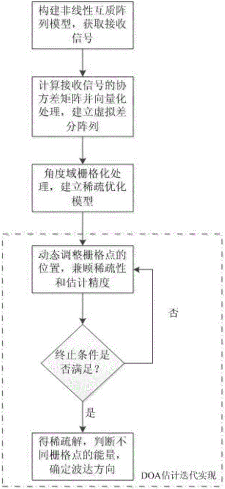
[0027] The flow chart of the inventive method is as figure 1 As shown, the specific implementation process is as follows:
[0028] (1) Construct a nonlinear coprime array model to obtain received signals;
[0029] (2) Calculate the covariance matrix of the received signal and perform vectorization processing to establish a virtual difference array;
[0030] (3) Rasterize the angle domain to establish a sparse optimization problem;
[0031] (4) Dynamically adjust the position of the grid points in an iterative manner until the termination condition is met. Analyze the sparse solution to determine the final direction of arrival.
[0032] The DOA estimation method process of the present invention is as follows:
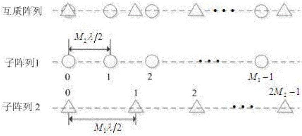
[0033] 1. Coprime array and its receiving signal
[0034] The coprime array involved in the present invention is such as figure 2 As shown, the arr...
PUM
 Abstract
Description
Claims
Application Information