
Automatic chip insertion machine

A chip inserter, fully automatic technology, applied in sustainable manufacturing/processing, electrical components, climate sustainability, etc., can solve the problems of high risk, difficult manual operation, easy to damage chip inserts, etc., to reduce the size of the equipment , Solve the effect of wire winding

Active Publication Date: 2016-10-12
ZHEJIANG UNIVERSITY OF SCIENCE AND TECHNOLOGY +1
View PDF7 Cites 10 Cited by
  • Summary
  • Abstract
  • Description
  • Claims
  • Application Information

AI Technical Summary

Problems solved by technology

The silicon wafers obtained after slicing are stacked together and need to be divided into pieces and inserted into the carrying box for transportation. Due to the thin and brittle characteristics of the silicon wafers, it is very easy to damage the inserted pieces manually, so the manual operation is very difficult. high risk, low efficiency

Method used


Image

  • Automatic chip insertion machine
  • Automatic chip insertion machine
  • Automatic chip insertion machine

Examples


Embodiment Construction

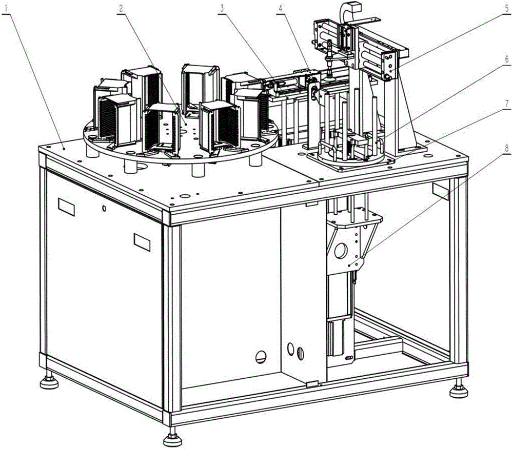
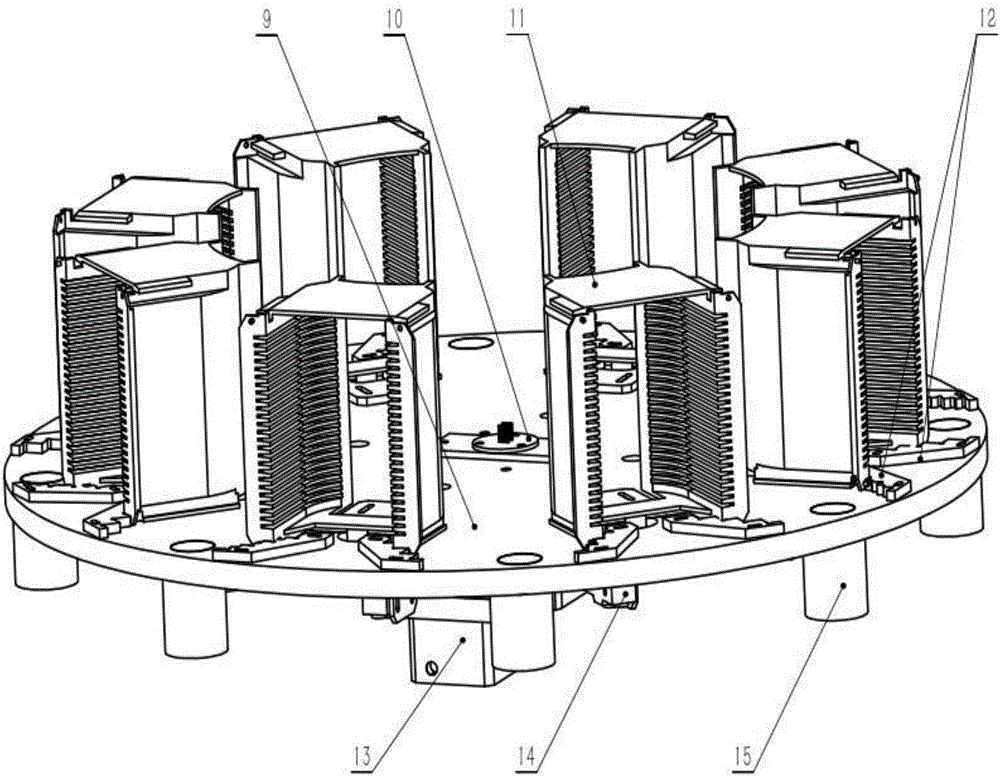
[0018] refer to figure 1 , figure 2 , image 3 , Figure 4 with Figure 5 , the present invention comprises equipment frame 1, blue tool rotating device 2, silicon wafer into blue device 3, blowing port 4, sucker pick-up device 5, silicon wafer box 6, fixed bottom plate 7, silicon wafer elevating device 8; Said equipment A tool rotating device 2 is installed on the left side of the upper end face of the frame 1, and the tool rotating device 2 includes a rotating disk 9, a conductive slip ring 10, a bearing box 11, a positioning block 12 of the bearing box, a hollow turntable 13, and a micro switch 14 and button switch 15, the conductive slip ring 10 is connected with the hollow turntable 13, the hollow turntable 13 is connected with the rotating disk 9, and the bearing box positioning block 12 is fixed on the rotating disk 9 by bolts; the lower right end of the equipment frame 1 is installed with Wafer lifting device 8, bottom plate 7 is installed on the upper right end o...


PUM


Abstract

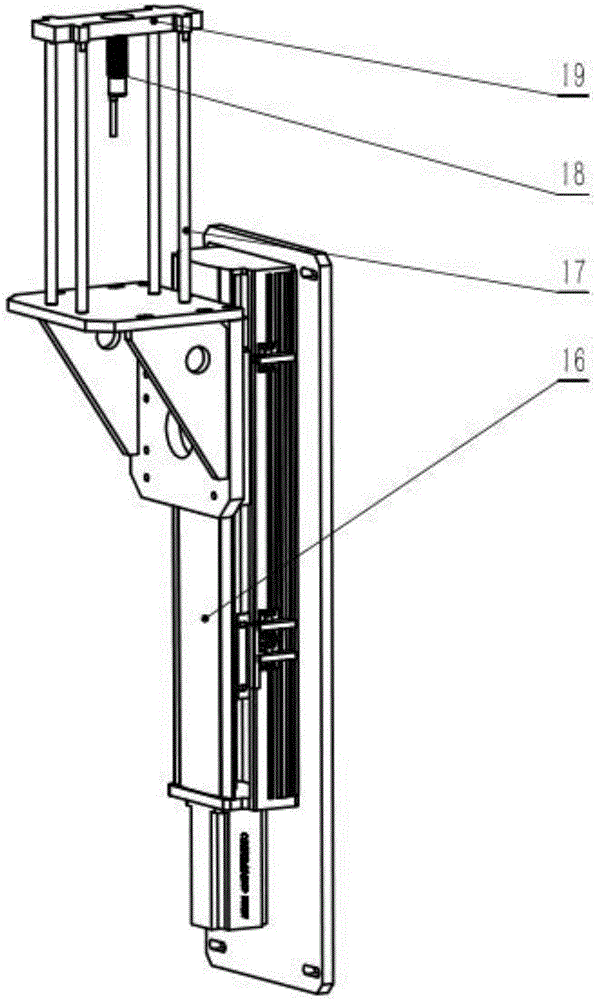
The present invention discloses an automatic chip insertion machine, which comprises a device rack, a basket tool rotating device, a silicon chip lifting device, an air blowing port, a silicon chip box, a fixed bottom plate, a sucking disc reclaiming device, and a silicon chip in-basket device. The basket tool rotating device is arranged on the device rack and comprises a hollow turntable, a conductive slip ring, a rotating disc, a button switch, a micro switch, a bearing box, and a bearing box positioning block. The conductive slip ring is connected with the hollow turntable. The hollow turntable is connected with the rotating disc. The bearing box positioning block is fixed onto the rotating disc through a bolt. The silicon chip lifting device comprises a material-ejection servo sliding table, a material-ejection supporting rod, a material-ejection block and a first detection switch. The material-ejection servo sliding table is connected with the material-ejection supporting rod. The material-ejection supporting rod is connected with the material-ejection block. When the automatic chip insertion machine is put to use, the manual operation of silicon chips is substantially abandoned, so that the manual chip-by-chip operation is avoided. Therefore, not only the breakage rate of silicon chips is reduced, but also the production efficiency is greatly improved.

Description

【Technical field】 [0001] The invention relates to the technical field of monocrystalline silicon production, in particular to the technical field of solar silicon chip processing equipment. 【Background technique】 [0002] Since the beginning of the 21st century, global energy consumption has risen sharply, and traditional fossil energy has been increasingly exhausted. Energy issues and environmental issues have initially become major issues of global concern. China has become the third largest natural gas consumer in the world, and traditional fossil energy has become increasingly difficult to meet the strong demand of my country's national economy. And in the past 20 years, about 75% of the world's man-made carbon dioxide emissions came from the burning of fossil fuels. Therefore, whether it is from the perspective of low-carbon environmental protection or in line with the pressure of upgrading and transformation of my country's industrial structure, my country must accele...

Claims


Application Information

Patent Timeline
Patent Type & Authority Applications(China)
IPC IPC(8): H01L31/18
CPCH01L31/1804H01L31/1876Y02P70/50
Inventor 侯继伟王黎航饶伟星
Owner ZHEJIANG UNIVERSITY OF SCIENCE AND TECHNOLOGY
Learn More