Directional coupler used for measuring microwave power of gyrotron traveling wave tube and manufacturing method for directional coupler

A directional coupler, microwave power technology, applied in the direction of waveguide type devices, electrical components, connecting devices, etc., can solve the problem of large influence of microwave absorption characteristics

Inactive Publication Date: 2016-10-12
NO 12 RES INST OF CETC
View PDF7 Cites 13 Cited by
  • Summary
  • Abstract
  • Description
  • Claims
  • Application Information

AI Technical Summary

Problems solved by technology

However, the measurement results are greatly affected by the ambient temperature and t...

Method used


Image

  • Directional coupler used for measuring microwave power of gyrotron traveling wave tube and manufacturing method for directional coupler
  • Directional coupler used for measuring microwave power of gyrotron traveling wave tube and manufacturing method for directional coupler
  • Directional coupler used for measuring microwave power of gyrotron traveling wave tube and manufacturing method for directional coupler

Examples


Embodiment 1

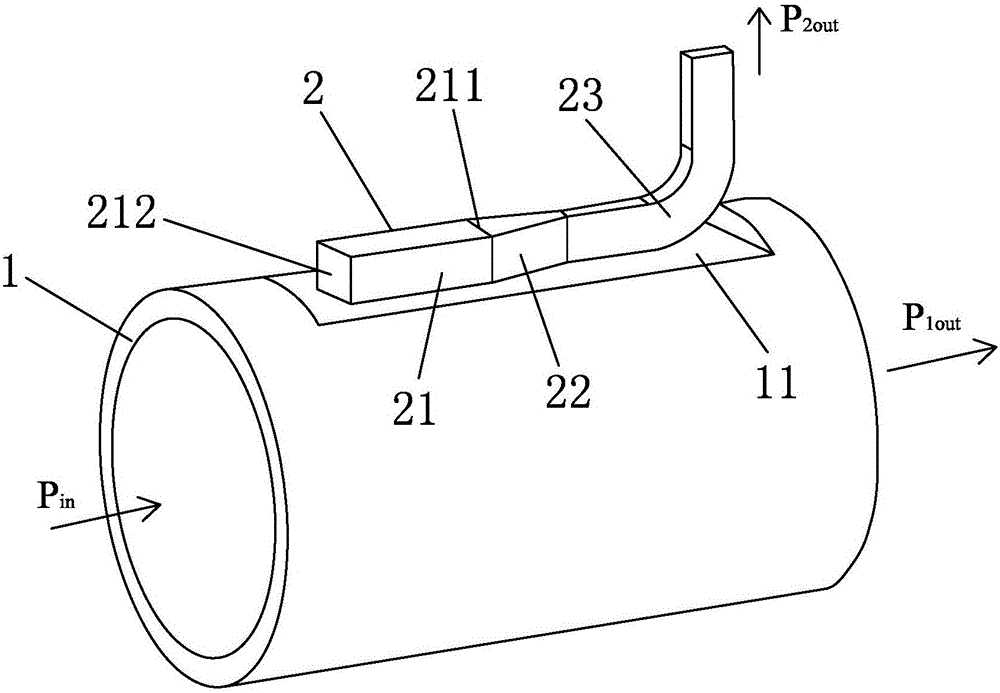
[0081] Such as Figures 1 to 4 As shown, a directional coupler for microwave power measurement of a gyrotron traveling wave tube, the coupler is a three-port device, which includes a main waveguide 1 and a matching secondary waveguide 2 arranged on the side wall of the main waveguide 1 , the outer surface 11 of the side wall of the circular waveguide 1 connected and fixed to the secondary waveguide 2 is arranged in a plane.

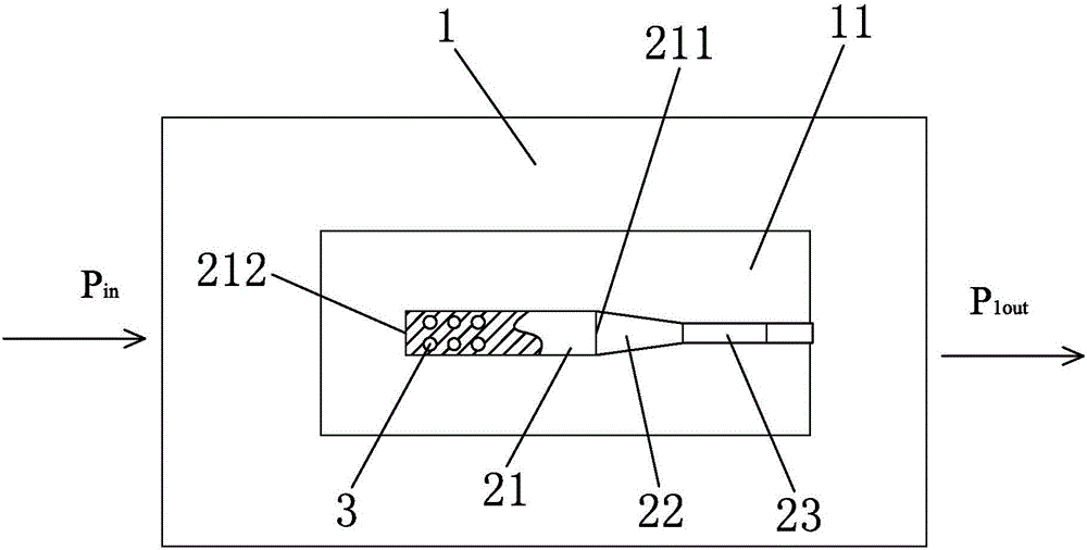
[0082] The main waveguide 1 has an input port P in and the output port P 1out The circular waveguide; the secondary waveguide 2 includes a square waveguide 21, a transition waveguide 22 and an output port P 2out a rectangular waveguide 23; the square waveguide 21 in the secondary waveguide 2 has one end port 211 connected to the transition waveguide 22, and the other end port 212 is a closed port, and the closed port 212 is also the closed port of the secondary waveguide 2;

[0083] Between the inner cavity of the circular waveguide and the inner cavit...

Embodiment 2

[0092] Such as Figures 1 to 6 Shown, the present invention provides a kind of manufacturing method of above-mentioned directional coupler, and this method comprises the following steps:

[0093] S1. According to the output characteristics of the gyrotron TWT and the power detection range of the measuring instrument, determine the design goal of the directional coupler, which includes the working frequency band, coupling degree and working bandwidth;

[0094]S2. According to the design goal of the directional coupler, determine the initial condition of the coupling hole on the directional coupler. The initial condition of the coupling hole includes the shape of the coupling hole and the distribution mode of the coupling hole; the shape of the coupling hole in this embodiment is a circle shape, the coupling holes are distributed in double rows along the axial direction of the circular waveguide;

[0095] S3. According to the shape of the coupling holes and the distribution mod...

Embodiment 3

[0119] Such as Figure 1 to Figure 4 , Figure 7 , 8 Shown, the present invention provides another kind of manufacturing method of above-mentioned directional coupler, and this method comprises the steps:

[0120] S1. According to the output characteristics of the gyrotron TWT and the power detection range of the measuring instrument, determine the design goal of the directional coupler, which includes the working frequency band, coupling degree and working bandwidth;

[0121] S2. According to the design goal of the directional coupler, determine the initial condition of the coupling hole on the directional coupler. The initial condition of the coupling hole includes the shape of the coupling hole and the distribution mode of the coupling hole; the shape of the coupling hole in this embodiment is a circle shape, the coupling holes are distributed in double rows along the axial direction of the circular waveguide;

[0122] S3. According to the shape of the coupling holes and...


PUM


Abstract

The invention discloses a directional coupler used for measuring microwave power of a gyrotron traveling wave tube. The directional coupler is a three-port device, which comprises a primary waveguide, a secondary waveguide which is correspondingly arranged on the side wall of the primary waveguide in a matched manner, wherein the primary waveguide is a circular waveguide comprising an input port Pin and an output port P1out; the secondary waveguide comprises a square waveguide, a transition waveguide and a rectangular waveguide which are sequentially connected, and the rectangular waveguide comprises an output port P2out; and a plurality of coupling holes, which realize power distribution between the primary waveguide and the secondary waveguide by utilizing a hole coupling method, are formed between an inner cavity of the circular waveguide and an inner cavity of the square waveguide in a penetrated manner. The directional coupler provided by the invention can realize the effect of reflecting variation situations of the microwave power of an electric vacuum amplification device in the millimeter-wave band immediately and accurately, and since the directional coupler is the three-port device, the output port P2out of the rectangular waveguide achieves the coupling from a circular waveguide TE01 Mode to a rectangular waveguide TE10 Mode.

Description

technical field [0001] The invention relates to a directional coupler for microwave power measurement of a cyclotron traveling wave tube and a manufacturing method for the directional coupler. Background technique [0002] The gyrotron is an electric vacuum amplifying device that works in the millimeter wave band. It can generate microwaves with a peak power of hundreds of kilowatts and an average power of several thousand watts in a wide frequency band (relative bandwidth of 10%). [0003] At present, the output microwave mode of the cyclotron traveling wave tube is the circular electric mode TE 01 For this mode, the power measurement method currently used is mainly the calorimeter method. The calorimeter method utilizes the characteristic that water has a strong absorption of microwaves. By measuring the water temperature change of the incoming and outgoing water load, the microwave power is obtained from the thermal power conversion formula P=CdvΔT, where C is the specif...

Claims


Application Information

Patent Timeline
IPC IPC(8): H01P5/18H01P11/00
CPCH01P5/181H01P11/00
Inventor 曾旭王峨锋冯进军李安
Owner NO 12 RES INST OF CETC
Why Eureka
Try Eureka