Protection system for voltage source type converter station, protection control system and protection method

A voltage source type, protection system technology, applied in emergency protection circuit devices, electrical components, etc., can solve the problems of manufacturing difficulty and high cost

Active Publication Date: 2016-10-12
NORTH CHINA ELECTRIC POWER UNIV (BAODING)
View PDF5 Cites 8 Cited by
  • Summary
  • Abstract
  • Description
  • Claims
  • Application Information

AI Technical Summary

Problems solved by technology

The fault current can reach 10-20 times of the rated current, and the DC circuit breaker needs to cut off such a large current within a few milliseconds, and its manufacturing difficulty and cost will be very high

Method used


Image

  • Protection system for voltage source type converter station, protection control system and protection method
  • Protection system for voltage source type converter station, protection control system and protection method
  • Protection system for voltage source type converter station, protection control system and protection method

Examples


Embodiment 1

[0047] A protection system for a voltage source converter station:

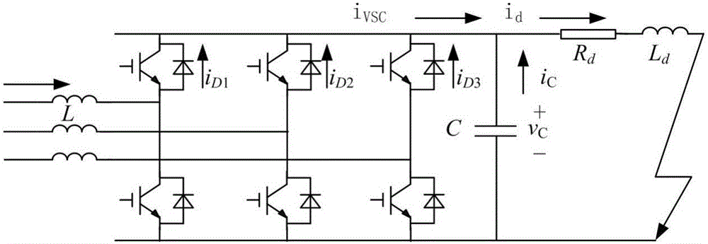
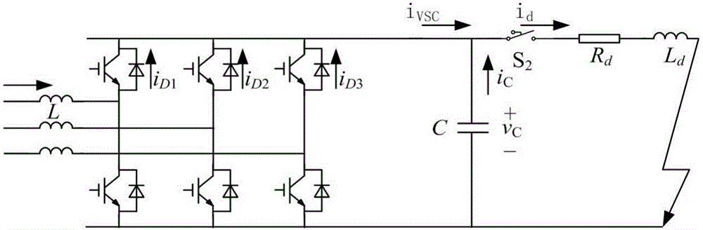
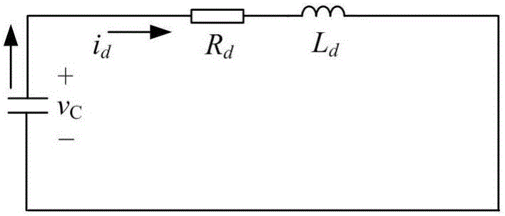
[0048] like Figure 5 As shown, the voltage source converter station includes a DC side capacitor, and when the DC side line is short-circuited, the DC side capacitor and the DC side line form an RLC second-order discharge circuit; the DC side of the voltage source converter station Fast switches S are installed before and after the side capacitors 1 and AC breaker B 1 , the fast switch S 1 At the moment t when the voltage of the DC link capacitor drops to zero 1 The previous action is to isolate the converter of the voltage source type converter station, and at the same time cause an oscillating current to be generated in the RLC second-order discharge circuit; the AC circuit breaker B 1 In the fast switch S 1 After the action, the oscillating current acts at the moment when it crosses zero, and cuts off the faulty line.

Embodiment 2

[0050] A protection control system for a voltage source converter station: including a fast switch control link and an AC circuit breaker control link; the fast switch control link receives a feedback signal from a fault detection system, and sets the time for identifying a DC side short-circuit fault as initial time t 0 , calculate the moment t when the voltage of the DC side capacitor drops to zero 1 , controls the fast switch S 1 At the moment t when the voltage of the DC link capacitor drops to zero 1 the moment before T 1 isolate the converter of the voltage source converter station, and at the same time set the fast switch S 1 The action moment T 1 As an instruction output to the AC circuit breaker control link, the AC circuit breaker control link will quickly switch S 1 The action moment T 1 As the initial moment, calculate the zero-crossing moment of the oscillating current generated in the RLC second-order discharge circuit, and control the AC circuit breaker B ...

Embodiment 3

[0053] A protection method for a voltage source type converter station, comprising the following steps:

[0054] Step 1: The Quick Switch S 1 At the moment t when the voltage of the DC link capacitor drops to zero 1 The previous action is to isolate the converter of the voltage source type converter station, and at the same time cause an oscillating current to be generated in the RLC second-order discharge circuit;

[0055] Step 2: The AC Breaker B 1 In the fast switch S 1 After the action, the oscillating current acts at the moment when it crosses zero, and cuts off the faulty line.

[0056] Further, in the step 1, the fast switch S 1 The action moment T 1 The calculation method consists of the following specific steps:

[0057] Step 1-1: Set the initial time t 0 The voltage v of the DC side capacitor after the fault C and current i L The initial condition is v C (t 0 ) = V 0 , i L (t 0 ) = I 0 , the voltage v of the DC side capacitor C The expression is:

[...


PUM


Abstract

The invention discloses a protection system for a voltage source type converter station, a protection control system and a protection method. A rapid switch mounted in front of a DC side capacitor is in matching with an AC breaker mounted at the back of the DC side capacitor, and rapid safe cut off of a fault line can be realized; when a short circuit fault occurs, a VSC transverter is rapidly isolated through the rapid switch, so damage to a freewheeling diode because of flowing in of a DC side fault current after discharging of the DC side capacitor can be avoided. After the rapid switch is opened, a second-order loop formed by the DC side capacitor and the fault line generates an oscillation current, so a current zero-crossing condition is provided for motion of the AC breaker, the fault current can be cut off by utilizing the low-cost AC breaker, and safety of the VSC transverter and a DC line is guaranteed.

Description

technical field [0001] The invention relates to a protection system, a protection control system and a protection method of a voltage source converter station, in particular to a protection system, a protection control system and a protection method of a voltage source converter station, belonging to the technical field of power supply protection. Background technique [0002] The DC power grid has no inherent problems of the AC power grid such as reactive power circulation and angle of attack stability, and has the advantages of flexibility and controllability, and has become a new direction for future power grid development. However, the protection technology for short-circuit faults on the DC side, especially bipolar short-circuit faults, is still immature, which has become one of the bottlenecks restricting the development of DC power grids. As the key equipment of the DC power grid protection system, the high-voltage DC circuit breaker plays an extremely important role ...

Claims


Application Information

Patent Timeline
Patent Type & Authority Applications(China)
IPC IPC(8): H02H7/26
CPCH02H7/268
Inventor 王毅付媛张紫光
Owner NORTH CHINA ELECTRIC POWER UNIV (BAODING)
Why Eureka
Try Eureka