Switched reluctance motor with 8/9 structure

A switched reluctance motor and magnet technology, applied in the direction of magnetic circuit shape/style/structure, magnetic circuit, electric components, etc., can solve the problems of motor winding end increase, motor output torque reduction, low utilization rate of iron core, etc. Achieve the effects of low core loss, reduced magnetomotive force, and high electromagnetic utilization.

Pending Publication Date: 2016-10-12
BRILLIANCE AUTO
View PDF0 Cites 11 Cited by
  • Summary
  • Abstract
  • Description
  • Claims
  • Application Information

AI Technical Summary

Problems solved by technology

[0003] In the traditional 8 / 6 structure switched reluctance motor, the two opposite excitation poles form a phase, and the magnetic flux path is long. The stator and rotor are double salient pole structures, and the magnetic flux will reverse during the commutation process of the motor rotation. , resulting in a decrease in the output torque of the motor, an increase in iron loss, an increase in wind friction loss, and a decrease in efficiency, etc.
Traditional segmented stator switched reluctance motor, low utilization rate of iron core, small torque
However, the traditional segmented rotor switched reluctance motor adopts distributed winding, which leads to the increase of the end of the motor winding and the increase of copper loss.
Therefore, in the design process of the motor structure, how to increase the output torque of the motor, reduce losses, and improve output efficiency has become a major obstacle in motor design.

Method used


Image

  • Switched reluctance motor with 8/9 structure
  • Switched reluctance motor with 8/9 structure
  • Switched reluctance motor with 8/9 structure

Examples


Embodiment Construction

[0012] Attached below Figure 1~4 And to describe the present invention in detail, the following description is only for demonstration and explanation, and does not limit the present invention in any form.

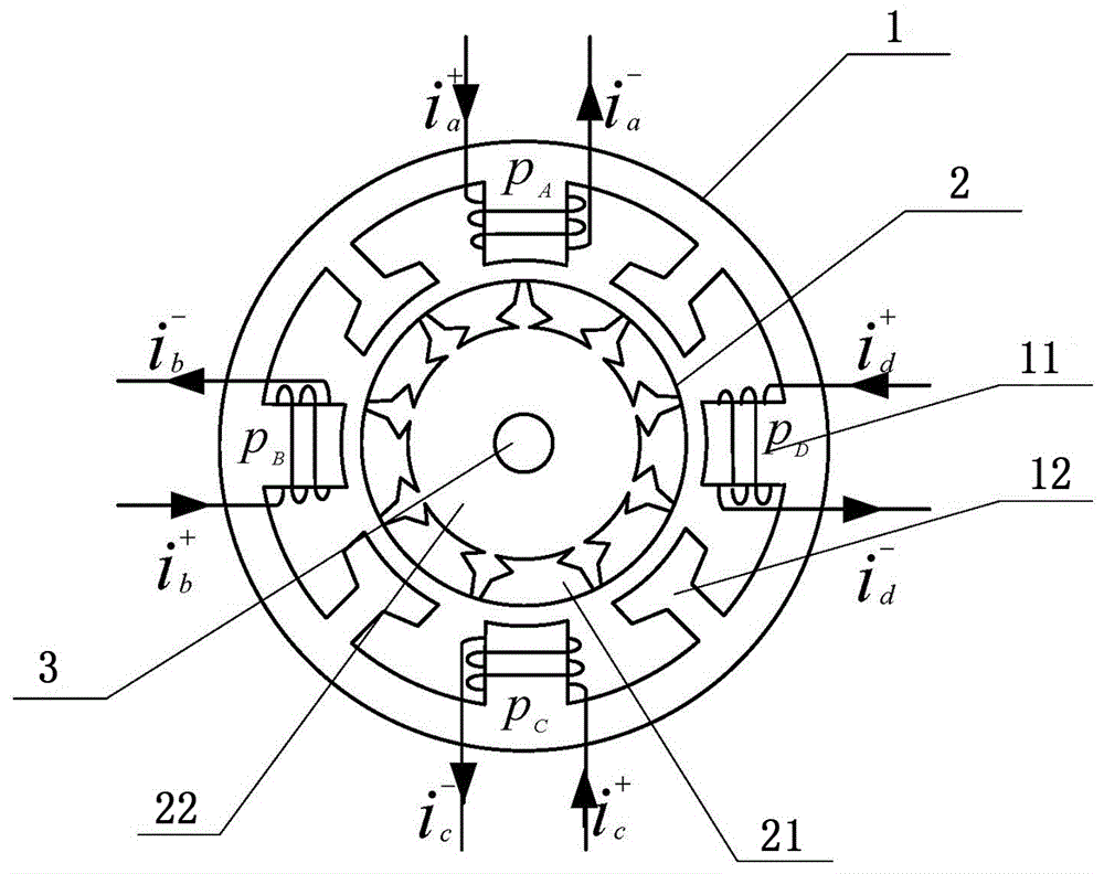
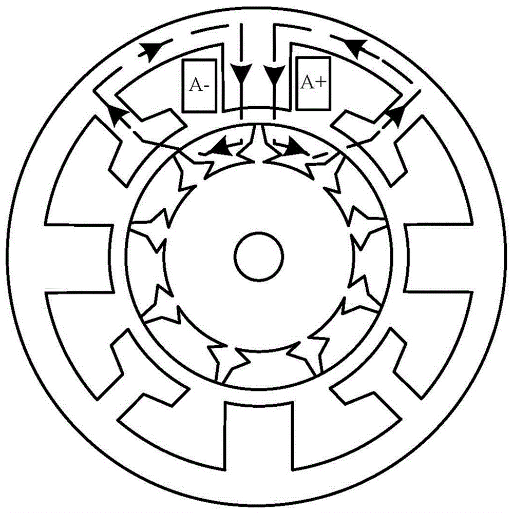
[0013] The technical solution of the present invention is: a switched reluctance motor with an 8 / 9 structure, including a housing, a stator 1 and a rotor 2, wherein the stator 1 is four-phase eight-pole, and the rotor 2 is nine-pole with block In the switched reluctance motor of the rotor, the stator 1 is fixed on the casing, and the stator 1 is alternately provided with excitation poles 11 and auxiliary poles 12, a total of eight, the width of the excitation pole 11 is twice the width of the auxiliary pole 12, and the excitation winding They are separately wound on the four excitation poles of A, B, C, and D. The rotor 2 includes nine independent rotor poles 21 and a non-magnetic conductor 22. Each rotor pole is evenly embedded in the non-magnetic conductor 22, and each i...


PUM


Abstract

The present invention relates to a switched reluctance motor with 8/9 structure. The switched reluctance motor provided by the invention is a block rotor equipped switched reluctance motor having a four-phase eight-pole stator and a nine-pole rotor. Fixedly arranged on the motor shell, the stator is provided with exciting poles and auxiliary poles alternately; the rotor comprises nine independent rotor poles and a non-conductive magnet. All the rotor poles are embedded in the non-conductive magnet evenly; each of the independent rotor poles forms an independent magnetic flux circuit with its adjacent exciting pole and auxiliary pole. The internal part of the rotor is provided with a motor shaft penetrating through the rotor center and driving the rotor to move. Because of the short flux path, there is no reversal of magnetic flux in the stator and rotor. In the process of motor rotating and phase changing, no negative torque will be generated. In addition, the motor adopts single-phase concentrated winding. The number of motor turns decreases; and required end winding is reduced so much that it can be neglected. Under the same input condition, the motor copper consumption is small, the core loss is small, the output torque is large, and therefore, the output efficiency of the motor is increased.

Description

technical field [0001] The invention relates to the field of reluctance motors manufactured by automobiles, in particular to a switched reluctance motor with an 8 / 9 structure. Background technique [0002] The research on switched reluctance motors started 150 years ago. Due to the development of microcontrollers in recent decades, switched reluctance motors have been widely concerned. Different from other types of motors, the switched reluctance motor is a double salient pole, single excitation motor with simple structure and good fault tolerance. Switched reluctance motors require a commutator to operate, so switched reluctance motors can operate at different speed levels. However, due to the shortcomings of switched reluctance motors such as large torque ripple and noise and low output torque, the market share of switched reluctance motors has been ignored. In order to compete with other types of motors, existing problems must be solved and the advantages of switched re...

Claims


Application Information

Patent Timeline
Patent Type & Authority Applications(China)
IPC IPC(8): H02K1/14H02K1/22
CPCH02K1/145H02K1/22
Inventor 张宏涛隋涛高力张玉龙卢明李凯陈全文邱爱娇呼延洪李亭亭贾茹李松
Owner BRILLIANCE AUTO
Why Eureka
Try Eureka