A myopic eye scanning module used for an optical coherence tomography instrument

An optical coherence tomography and scanning module technology, applied in the field of optical medical treatment, can solve the problems of increased maximum optical path difference, small signal-to-noise ratio, and reduced scanning signal, and achieves the effect of avoiding errors

Inactive Publication Date: 2016-10-19
CARL ZIESS MEDITEC INC
View PDF5 Cites 2 Cited by
  • Summary
  • Abstract
  • Description
  • Claims
  • Application Information

AI Technical Summary

Problems solved by technology

If the distance adjustment between the retinal scanning lens and the eyepiece is used, refractive error correction can be performed, however, for a myopic eye with an elongated eye axis, the focusing angle of a single scanning beam is smaller than that of a refractive normal eye, As a result, the numerical aperture of the entire system becomes smaller, resulting in a decrease in the intensity of the scanned signal obtained relative to the case of the normal eye, and a smaller signal-to-noise ratio of th

Method used


Image

  • A myopic eye scanning module used for an optical coherence tomography instrument
  • A myopic eye scanning module used for an optical coherence tomography instrument
  • A myopic eye scanning module used for an optical coherence tomography instrument

Examples


Embodiment Construction

[0044] An optical coherence tomography scanner according to an embodiment of the present invention is described below with reference to the accompanying drawings. In the following description, numerous specific details are set forth in order to enable those skilled in the art to fully understand the present invention. It will be apparent, however, to one skilled in the art that the present invention may be practiced without some of these specific details. Furthermore, it should be understood that the invention is not limited to the particular embodiments described. Instead, it is conceivable to implement the present invention in any combination of the following features and elements, regardless of whether they relate to different embodiments. Accordingly, the following aspects, features, embodiments and advantages are by way of illustration only and should not be considered elements or limitations of the claims unless explicitly stated in the claims.

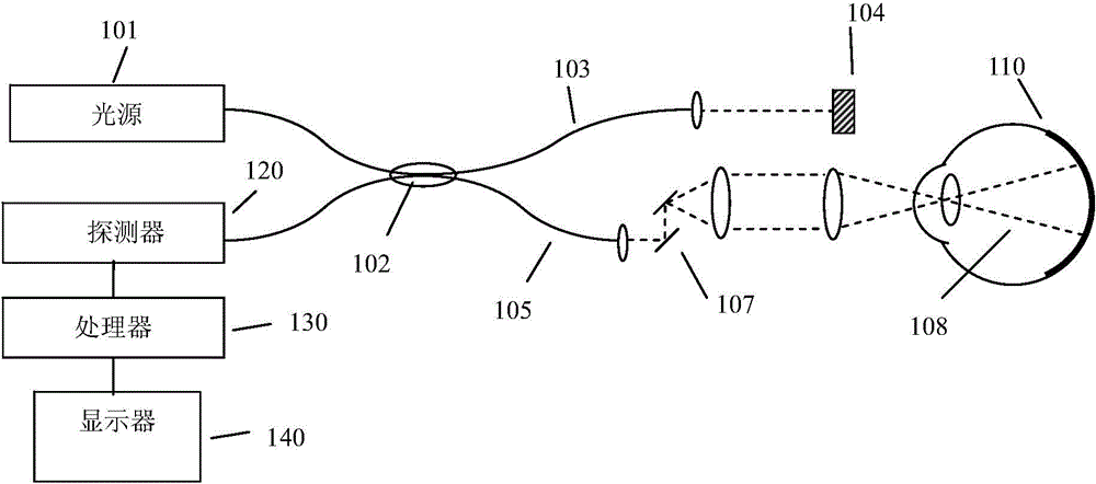
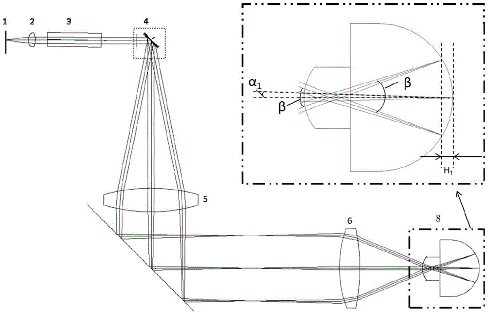
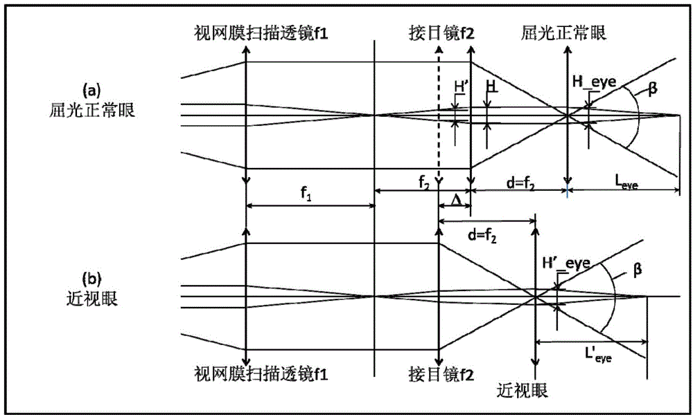
[0045] Figure 7 An o...


PUM


Abstract

An optical coherence tomography instrument comprises an optical coherence tomography module used for retina scanning for emmetropia eyes and a myopic eye scanning module which can be attached to the outside of the optical coherence tomography module to realize switching of a scanning function for emmetropia eyes and a scanning function for myopic eyes with elongating ocular axes of the optical coherence tomography instrument. The myopic eye scanning module has a negative focal power, so that scanning light beams from the optical coherence tomography instrument are diffused before entering myopic eyes with elongating ocular axes and further the focusing angle of scanning light beams focused on retinas of the myopic eyes with elongating ocular axes is increased and the maximum optical path difference spanned by imaging areas of the retinas is reduced. Thus, error-free mirror image scanning images with stronger scanning signals and higher signal-to-noise ratios can be obtained.

Description

technical field [0001] The invention relates to the field of optical medicine, in particular to an optical coherence tomography scanner (OCT System, Optical Coherence Tomography System) with a myopia scanning module. Background technique [0002] Optical coherence tomography is an interferometry method used to obtain the scattering properties of a sample being scanned. Optical coherence tomography can be divided into time domain optical coherence tomography (TD-OCT) and frequency domain optical coherence tomography (FD-OCT). Compared with time-domain optical coherence tomography, frequency-domain optical coherence tomography has obvious advantages in terms of speed and signal-to-noise ratio. Discrimination of spectral information in frequency-domain optical coherence tomography is usually achieved by: in the case of spectral-domain optical coherence tomography (SD-OCT), the spectrometer in the detection arm can be used for spectroscopy; In the case of optical coherence tom...

Claims


Application Information

Patent Timeline
IPC IPC(8): A61B3/14A61B3/10
CPCA61B3/102A61B3/1225G01B9/02063G01B9/02091
Inventor 郭小娴丘悦裴马丁
Owner CARL ZIESS MEDITEC INC
Why Eureka
Try Eureka