Method for estimating flow by means of radar wave flow meter

A technology of current measuring instrument and radar wave, which is applied in the field of estimating flow rate by using radar wave current measuring instrument, can solve the problems of section area error, river gradient error, and high measurement requirements, so as to eliminate error, reduce cost and complexity, high precision effect

Inactive Publication Date: 2016-10-19
XIAN SUMMIT TECH
7 Cites 17 Cited by

AI-Extracted Technical Summary

Problems solved by technology

[0021] 2. Roughness error
[0023] 3. River slope error
[0025] 4. Sectional area error
[0028] (1) There are systematic errors: As analyzed above, since the four calculation parameters are more or less approximate calculations or inevitably introduce errors in the laboratory measurement process, there are systematic errors in the entire flow calculation process. At the same time, these Errors are intersecting and influencing each other, so the overall errors may partly cancel each other out, or they may accumulate together and be further amplified
[...

Abstract

The invention provides a method for estimating flow rate by using a radar current measuring instrument, comprising the following steps: 1) measuring surface flow velocity; 2) calculating synthetic surface flow velocity; 3) calculating average flow velocity; 4) calculating flow rate. The present invention calculates the average flow velocity by establishing the corresponding functional relationship between the surface flow velocity and the average flow velocity, and does not use the Manning formula to calculate the average flow velocity. The present invention needs to measure less data when calculating the flow rate, avoids the inevitable error caused by the measurement to a certain extent, and reduces the cost and complexity required for calculating the flow rate. When the relationship between flow rate, more fitting functions can be used, which has good scalability.

Application Domain

Technology Topic

Manning formulaEnvironmental geology +3

Image

  • Method for estimating flow by means of radar wave flow meter
  • Method for estimating flow by means of radar wave flow meter
  • Method for estimating flow by means of radar wave flow meter

Examples

  • Experimental program(1)

Example Embodiment

[0077] The present invention will be further introduced below in conjunction with the drawings, but the present invention is not limited by specific embodiments.
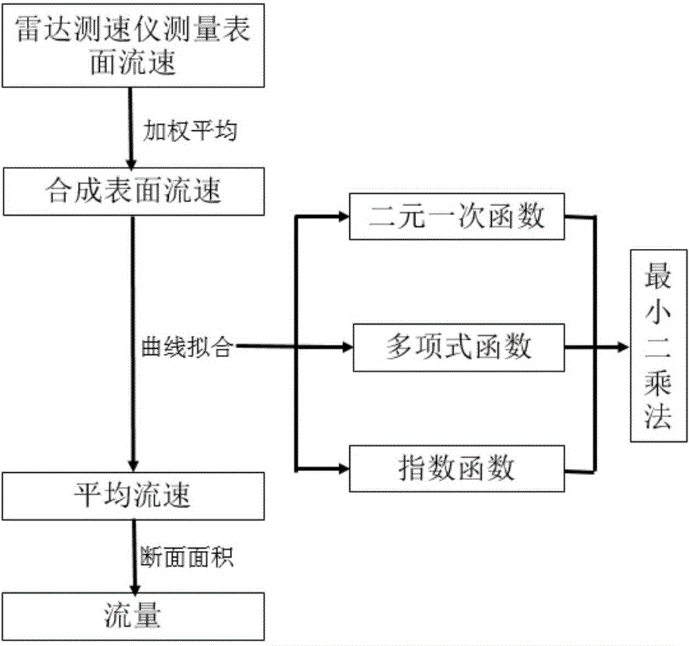
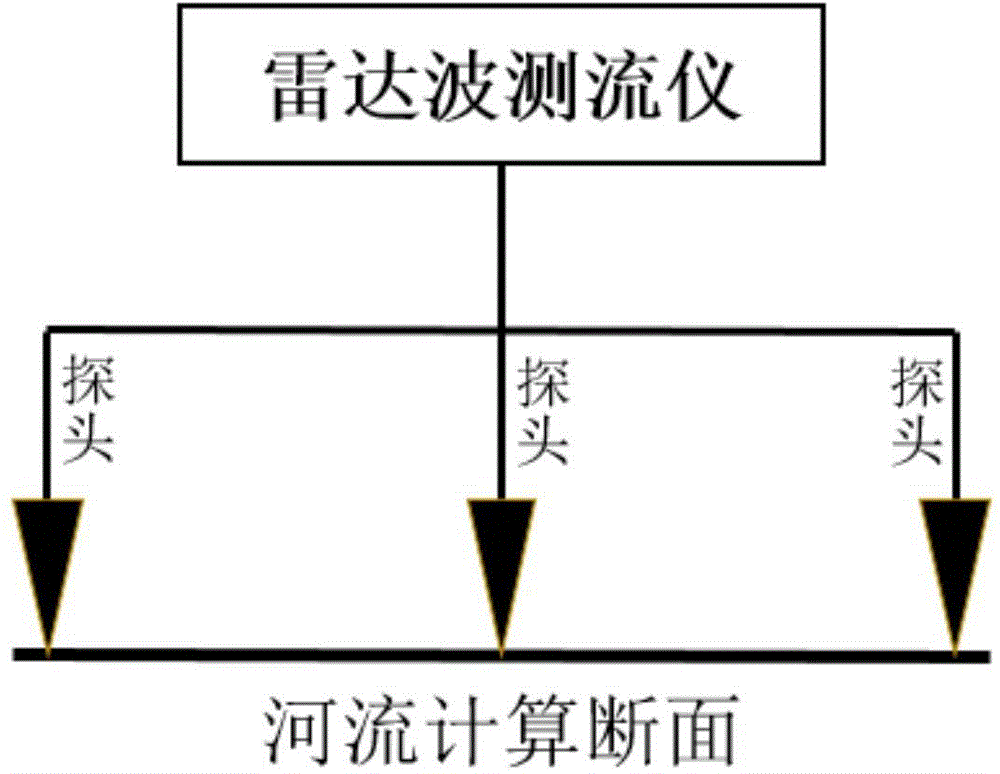
[0078] 1. Surface velocity measurement
[0079] Such as figure 2 As shown, the radar wave flow meter generally has multiple probes. Let’s take three probes as an example. These three probes will measure three surface velocities at a certain moment, which we denote as V1, V2, and V3. , These three probes will measure multiple sets of data, which we denote as 1(V1, V2, V3), 2(V1, V2, V3),..., n(V1, V2, V3), of which 1, 2,... , N represents different moments.
[0080] 2. Calculation of synthetic surface velocity
[0081] For the three surface velocities at a certain moment, we take the first moment 1 (V1, V2, V3) as an example. We can artificially set three probes according to the height and position of each probe and the relevant conditions of the river itself. For example, the weight values ​​corresponding to the three flow rates are respectively P1, P2, and P3, where P1+P2+P3=1. Then we can get the synthetic surface velocity at this moment according to the three surface velocity, as shown in the following formula: V Combine 1 =V1*P1+V2*P2+V3*P3. In the same way, the synthetic surface velocity V at n times can be calculated In 1 , V In 2 ,..., V Close.
[0082] 3. Calculation of average flow rate
[0083] (1) Compile data
[0084] Through steps 1 and 2, we have obtained the synthesized surface velocity value (V In 1 , V In 2 ,..., V Close ), at the same time, we measured the actual average flow velocity (V Average 1 , V Average 2 ,..., V Average n ). Therefore, we have obtained n sets of average velocity and synthetic surface velocity data (V In 1 , V Average 1 ), (V In 2 , V Average 2 ), ..., (V Close , V Average n ). We organize the data into the above format.
[0085] (2) Derivation of functional relationship
[0086] With multiple sets of average flow velocity and synthetic surface flow velocity data, we can use curve fitting related principles to derive the functional relationship between the two. The present invention provides three types of functional relationships between binary linear equations, polynomial equations and exponential equations as The assumed correlation between the average flow velocity and the synthetic surface flow velocity, and then the undetermined parameters are obtained by the least square method. Take the unary linear function as an example to briefly explain this process:
[0087] It is assumed that there is a one-dimensional linear function relationship between the average velocity and the composite surface velocity, that is, the linear function V average = AV Combine +b. But the parameters a and b are to be determined. According to the principle of least square method, the measured value V Average i And calculated value V Calculate i= aV 合i The sum of squared deviations of +b is the smallest that is Φ=∑(V Average i -V Calculate i ) 2 The smallest is the optimal one-variable linear equation, that is, the most accurate basis for judging the functional relationship between the average velocity and the composite surface velocity, when ∑(V Average i -V Calculate i ) 2 At the minimum, the partial derivative of the Φ function with respect to a and b can be obtained, and the partial derivative is equal to 0 to obtain the values ​​of a and b, as shown below:
[0088] ∑2V 合i (V Average i -aV 合i -b)=0 (15)
[0089] ∑2(V Average i -aV 合i -b)=0 (16)
[0090] Then the n sets of data (V In 1 , V Average 1 ), (V In 2 , V Average 2 ), ..., (V Close , V Average n ) Bring in the above two formulas to obtain the values ​​of the parameters a and b, so that the functional relationship between the average flow velocity and the synthetic surface flow velocity is established. Of course, the two-variable linear function relation, the one-variable quadratic function relation, the one-variable cubic function relation, and the exponential function relation can be obtained in the same way.
[0091] (3) Obtain the optimal relationship
[0092] After (2) we have obtained a variety of functional relations between the two, we choose the best one as the final functional relation between the average flow velocity and the synthetic surface flow velocity. The optimal judgment basis is the mean square error of the calculation result. The formula is as follows:
[0093]
[0094] 4. Flow calculation
[0095] After step (3), we can use the synthetic surface flow rate to calculate the average flow rate V through a functional relationship, such as image 3 As shown, we are calculating the section ( image 3 Two sections are set at a certain distance upstream and downstream of the interrupted surface in the middle, and then the average of the three section areas is used as the final average section area A of the calculated section, and finally the flow value is calculated by Q=A*V.
[0096] The above description is only for the preferred embodiments of the present invention and is not intended to limit the present invention. For those skilled in the art, the present invention may have various modifications and changes. Any modification, equivalent replacement, improvement, etc. made within the scope of the claims of the present invention shall fall within the protection scope of the present invention.

PUM

no PUM

Description & Claims & Application Information

We can also present the details of the Description, Claims and Application information to help users get a comprehensive understanding of the technical details of the patent, such as background art, summary of invention, brief description of drawings, description of embodiments, and other original content. On the other hand, users can also determine the specific scope of protection of the technology through the list of claims; as well as understand the changes in the life cycle of the technology with the presentation of the patent timeline. Login to view more.

Similar technology patents

Method for detecting phthalate ester plasticizer in plastic

Owner:DALIAN INST OF CHEM PHYSICS CHINESE ACAD OF SCI

Classification and recommendation of technical efficacy words

  • Easy to carry
  • Reduce volume

Display device

ActiveCN103914273AEasy to carryBig viewing screenDigital output to display deviceIdentification meansEngineeringFlexible display
Owner:BOE TECH GRP CO LTD

Treatments of therapy resistant diseases and drug combinations for treating the same

InactiveUS20080312199A1Accurately predict resistanceEasy to carryAntibacterial agentsBiocideCancers diagnosisMesothelioma
Owner:ORDWAY RES INST

Implant release mechanism

ActiveUS20080140178A1Reduce volumeReduce outer diameterStentsOcculdersDilatorStent
Owner:COOK MEDICAL TECH LLC

Flash storage chip and flash array storage system

ActiveUS20080052451A1Reduce volumeImprove data transmission rateMemory adressing/allocation/relocationData transmissionPCI Express
Owner:PHISON ELECTRONICS

Devices and methods for placement of partitions within a hollow body organ

InactiveUS20070167960A1Reduce volumeSuture equipmentsStapling toolsTissue acquisitionBody organs
Owner:ETHICON ENDO SURGERY INC
Why Eureka
Try Eureka