Automatic cleaning equipment

A technology for automatic cleaning and equipment, applied in cleaning methods and utensils, cleaning methods using tools, chemical instruments and methods, etc., can solve the problems of increasing production costs and bulky cleaning devices, and achieve low production costs and good cleaning effects , the effect of high degree of automation

Inactive Publication Date: 2016-10-26
苏州誉衡兴自动化科技有限公司
View PDF6 Cites 14 Cited by
  • Summary
  • Abstract
  • Description
  • Claims
  • Application Information

AI Technical Summary

Problems solved by technology

[0002] With the continuous development of science and technology, assembly line production has become a symbol of industrial production. In assembly line production, it is often necessary to clean the outer surface of the finished product and then put it into storage. There are many cleaning methods at present. Many small enterprises want to save costs. , so that manual cleaning is adopted, and some cleaning devices include many parts, such as: spraying device, cleaning parts and drying parts, etc., which makes the whole cleaning device bulky and greatly increases production costs. Therefore, a simple structure is required. , Small size, low cost automatic cleaning device

Method used


Image

  • Automatic cleaning equipment

Examples


Embodiment Construction

[0015] In order to make the object, technical solution and advantages of the present invention more clear, the present invention will be further described in detail below in conjunction with the examples. It should be understood that the specific embodiments described here are only used to explain the present invention, not to limit the present invention.

[0016] The application principle of the present invention will be described in detail below in conjunction with the accompanying drawings.

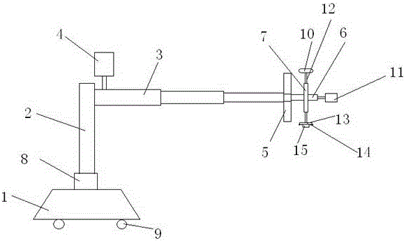
[0017] Such as figure 1 As shown, a kind of automatic cleaning equipment comprises base 1, column 2, telescopic bar 3, cleaning device; Described column 2 is installed on the base, and described telescopic bar 3 is driven by first motor 4, and one end thereof Link to each other with the top of column 2; Described cleaning device comprises first supporting plate 5, rotating shaft 6, runner 7, spray washing head, cleaning head, air dryer 10, one side of first supporting plate 5 and tele...


PUM


Abstract

The invention discloses automatic cleaning equipment. The automatic cleaning equipment comprises a base, a stand column, an extendable and retractable cross rod and a cleaning device. The stand column is mounted on the base. The extendable and retractable cross rod is driven by a first motor, and one end of the extendable and retractable cross rod is connected with the top end of the stand column. The cleaning device comprises a first carrying plate, a rotating shaft, a rotating wheel, spraying heads, a cleaning head and an air drying machine. One face of the first carrying plate is connected with the other end of the extendable and retractable cross rod. The other face of the first carrying plate is connected with one end of the rotating shaft through a bearing. The rotating shaft is driven by a second motor. The rotating wheel is arranged at the outer side of the rotating shaft in a sleeving manner. The rotating wheel is provided with two connecting rods, wherein one connecting rod is connected with the cleaning head, and the other connecting rod is connected with the air drying machine. The cleaning head comprises a cleaning plate body, distance sensors and a brush head, wherein the distance sensors are arranged at the periphery of the cleaning plate body; and the brush head is arranged in the middle of the cleaning plate body. The spraying heads are arranged at the periphery of the cleaning plate body. The automatic cleaning equipment is simple in structure, small in size, low in production cost, high in automation degree, good in cleaning effect and high in precision.

Description

technical field [0001] The invention belongs to the technical field of cleaning equipment, and in particular relates to an automatic cleaning equipment. Background technique [0002] With the continuous development of science and technology, assembly line production has also become a symbol of industrial production. In assembly line production, it is often necessary to clean the outer surface of the finished product before storing it in storage. There are many cleaning methods at present. Many small enterprises want to save costs. , so that manual cleaning is adopted, and some cleaning devices include many parts, such as: spraying device, cleaning parts and drying parts, etc., which makes the whole cleaning device bulky and greatly increases production costs. Therefore, a simple structure is required. , Small size, low cost automatic cleaning device. Contents of the invention [0003] In view of the above problems, the present invention proposes an automatic cleaning devi...

Claims


Application Information

Patent Timeline
Patent Type & Authority Applications(China)
IPC IPC(8): B08B1/00B08B13/00
CPCB08B1/002B08B1/005B08B13/00
Inventor 刘舜川
Owner 苏州誉衡兴自动化科技有限公司
Why Eureka
Try Eureka