
Position compensation device and method in annular rolled piece machining process

A technology of compensation device and compensation method, which is applied in the direction of rolling mill control device, metal processing equipment, metal rolling, etc.

Active Publication Date: 2016-10-26
YANSHAN UNIV
View PDF6 Cites 4 Cited by
  • Summary
  • Abstract
  • Description
  • Claims
  • Application Information

AI Technical Summary

Problems solved by technology

[0004] Aiming at the problem of inaccurate and distorted on-line dimension detection during the processing of ring-rolled pieces, the present invention provides a method for on-line real-time detection and position compensation, thereby solving the technical problem of accurate on-line dimension detection during the processing of ring-rolled pieces

Method used


Image

  • Position compensation device and method in annular rolled piece machining process
  • Position compensation device and method in annular rolled piece machining process
  • Position compensation device and method in annular rolled piece machining process

Examples


Embodiment Construction

[0046] The present invention will be further described in detail below in conjunction with the accompanying drawings and specific embodiments.

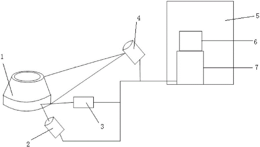
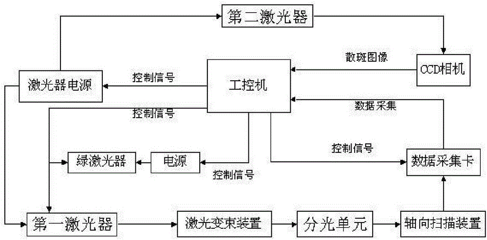
[0047] figure 1 Shown is the position compensation device of the ring rolling piece of the present invention, which uses a laser to detect the size of the ring rolling piece online, including: a laser scanning unit 4, which collects the data of the ring rolling piece 1 during the rolling process; laser speckle imaging A unit, which is synchronized with the laser scanning unit 4, forms a speckle image on the surface of the ring rolling piece 1; and a control unit 7, which controls the laser scanning unit 4 and the laser speckle imaging unit, based on the data collected by the laser scanning unit 4 and the speckle image formed by the laser speckle imaging unit to calculate the radius compensation amount of the ring rolling piece 1 . Since the radius of the ring rolling piece 1 gradually increases during the rolling process, it is neces...


PUM


Abstract

The invention provides a position compensation device in the annular rolled piece machining process. The position compensation device uses laser to detect the size of an annular rolled piece in an on-line mode and comprises a laser scanning unit, a laser speckle imaging unit and a control unit. The laser scanning unit collects data of the annular rolled piece in the rolling process, the laser speckle imaging unit and the laser scanning unit are synchronous, and a speckle image is formed on the surface of the annular rolled piece; and the control unit controls the laser scanning unit and the laser speckle imaging unit, and the position compensation quantity of the annular rolled piece is calculated based on the data collected by the laser scanning unit and the speckle image formed by the laser speckle imaging unit. The invention further provides a position compensation method in the annular rolled piece machining process. According to the position compensation device and method in the annular rolled piece machining process, the size of the annular rolled piece which is subjected to grinding and expansion can be measured, the difference value of the radius change of the annular rolled piece can be compensated, and accordingly cross section restoration of the annular rolled piece can be achieved.

Description

technical field [0001] The invention relates to the detection field of the ring rolling piece production process, in particular to a position compensation device and a position compensation method in the ring rolling piece processing process. Background technique [0002] The on-line detection of ring rolling piece size is a very typical and important link in the ring rolling piece production process. During the forging process of the ring-rolled piece, the online measurement of the size of the ring-rolled piece can measure whether the ring-rolled piece meets the process requirements, thereby reducing the scrap rate, so the method of online detection of the ring-rolled piece size has attracted more and more attention at home and abroad and attention. [0003] The difficulty of on-line detection of the size of the ring-rolled piece mainly lies in the dynamics of the ring-rolled piece during the rolling process, the measured diameter of the ring-rolled piece increases with th...

Claims


Application Information

Patent Timeline
IPC IPC(8): B21B37/16
CPCB21B37/16
Inventor 张玉存王永杰徐飞田梦琦
Owner YANSHAN UNIV
Learn More