
3D printing method of low melting point metal fused deposition based on continuous fiber pulling

A low-melting-point metal, continuous fiber technology, applied in the field of metal 3D printing, can solve the problems of difficult to form fine structures, large droplet volume, restricted development space, etc., to avoid internal defects, improve mechanical properties and functionality. , the effect of improving print resolution and accuracy

Active Publication Date: 2018-03-16
XI AN JIAOTONG UNIV
View PDF6 Cites 0 Cited by
  • Summary
  • Abstract
  • Description
  • Claims
  • Application Information

AI Technical Summary

Problems solved by technology

[0003] However, there are two extremely critical technical problems in the current low-melting point metal 3D printing method, which greatly restricts its development space:
[0004] 1. At room temperature, the surface tension of most liquids is below 100 dynes / cm, while the surface tension of liquid metals can reach hundreds or even thousands of dynes / cm. The volume of the droplet formed at the outlet will be very large, so that its gravity can overcome the tension and deposit on the bottom surface freely. Therefore, the accuracy of 3D printing will be limited by these larger droplets, and it is difficult to form fine the structure;
[0005] 2. Different from the viscous flow state of thermoplastic materials used for fused deposition 3D printing, low-melting point metal materials are in a liquid state with better fluidity in the molten state. Therefore, liquid metal is easier to flow and diffuse during the deposition process, which will make 3D The controllability of printing is greatly reduced, and at the same time, due to the large surface tension, liquid metal is more likely to form liquid agglomeration during deposition

Method used


Image

  • 3D printing method of low melting point metal fused deposition based on continuous fiber pulling

Examples


Embodiment Construction

[0017] The present invention will be further described in detail below in conjunction with the accompanying drawings.

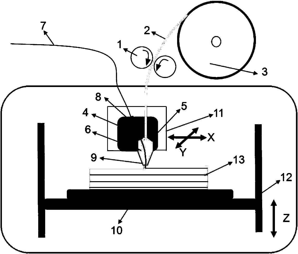
[0018] 1) Refer to figure 1 , the wire feed roller 1 pulls the low-melting point metal wire 2 out of the wire tray 3, and feeds it into the 3D printing head 4 connected to the XY mechanical movement mechanism 11, and melts it in the melting chamber 5 of the 3D printing head 4 Liquid metal 6, the low-melting point metal wire 2 is Bi, Sn, Pb or In-based alloy; at the same time, the continuous fiber filament 7 enters the melting chamber 5 through the microporous channel 8 of the 3D printing head 4, the described Continuous fiber filament 7 is carbon fiber, glass fiber, metal fiber or organic synthetic fiber;

[0019] 2) The continuous fiber filament 7 in the melting chamber 5 is infiltrated with the liquid metal 6, and is extruded from the nozzle 9 of the 3D printing head 4 together. Under the traction of the continuous fiber filament 7, the liquid metal 6 does...


PUM

PropertyMeasurementUnit
surface tensionaaaaaaaaaa

Abstract

The low melting point metal fused deposition 3D printing method based on continuous fiber traction uses continuous fiber filaments as the traction line for liquid metal extrusion deposition, so that the liquid metal is attached to the continuous fiber filaments and continuously extruded following the continuous fiber filaments, avoiding metal The formation of large droplets greatly improves the printing resolution; at the same time, during the deposition and solidification process, the continuous fiber filaments can bind the diffusion of liquid metal, thereby improving the precision of the parts, avoiding excessive structural defects, and improving the printing quality to a certain extent. The mechanical properties and functionality of parts, thus promoting the development and application of metal 3D printing technology.

Description

technical field [0001] The invention relates to the technical field of metal 3D printing, in particular to a 3D printing method for fused deposition of low melting point metals based on continuous fiber traction. Background technique [0002] The low-melting-point metal 3D printing method generally refers to the use of liquid low-melting-point metal ink in the molten state as the 3D printing material, through a special 3D printing nozzle, under the precise control of the three-dimensional motion mechanical system, extruding and spraying on the bottom plate or the previous one. On the metal material, it is cooled and solidified under the action of air or liquid coolant, so that the layers are accumulated and formed for 3D printing of metal parts (a low melting point metal 3D printing device, Chinese patent CN203992400U[P].2014.). This 3D printing method is a low-cost, high-efficiency additive manufacturing method that can directly manufacture metal parts, electronic circuits ...

Claims


Application Information

Patent Timeline
Patent Type & Authority Patents(China)
IPC IPC(8): B22F3/115B33Y30/00B33Y10/00
CPCB22F3/003B22F3/115B33Y10/00B33Y30/00
Inventor 李涤尘杨春成田小永曹毅
Owner XI AN JIAOTONG UNIV
Learn More