
Numerically-controlled finish-milling device and finish-milling method for steel rail weld joints

A rail and precision milling technology, applied to milling machine equipment, milling machine equipment details, metal processing equipment, etc., can solve problems such as high labor intensity, processing error scrap rate, and inconvenient replacement of faulty maintenance parts

Active Publication Date: 2016-10-26
深圳市高能精密机械有限公司
View PDF6 Cites 7 Cited by
  • Summary
  • Abstract
  • Description
  • Claims
  • Application Information

AI Technical Summary

Problems solved by technology

Due to the obsolete equipment of various railway bureaus, the traditional methods of removing weld bumps are mostly manual use of hand grinding wheels and CNC machining. However, the manual hand grinding wheel method has high labor intensity and low efficiency, and the grinding gravel and metal dust are massively absorbed by the human body Inhalation is extremely harmful to the human body; the method of CNC milling machine processing cannot solve the phenomenon of head-turning during rail welding, which is easy to damage the original rail and requires tool calibration for each processing, resulting in low efficiency and high scrap rate due to processing errors
At present, more than ten rail welding factories in China are mostly importing advanced weld fine grinding machines from abroad. These advanced fine grinders have greatly improved the working environment and labor intensity of operators, and also improved the grinding quality of weld seams. However, the price of imported fine grinding machines is high, and it is very inconvenient to repair faults and replace parts. It is restricted by people and the cost is huge

Method used


Image

  • Numerically-controlled finish-milling device and finish-milling method for steel rail weld joints
  • Numerically-controlled finish-milling device and finish-milling method for steel rail weld joints
  • Numerically-controlled finish-milling device and finish-milling method for steel rail weld joints

Examples


Embodiment 1

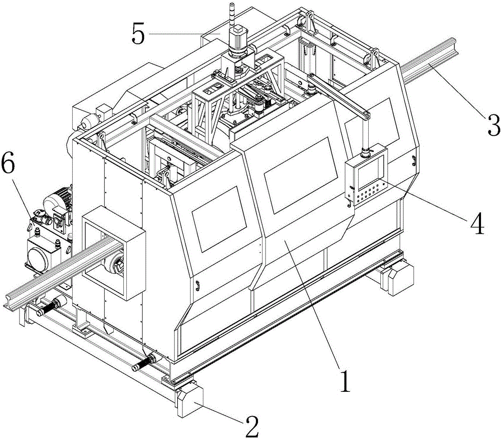
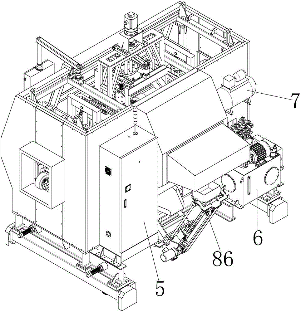
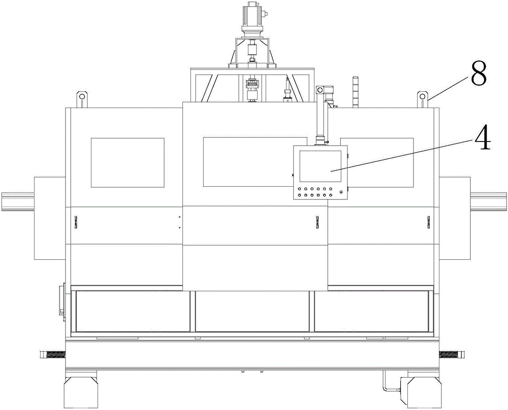
[0083] Embodiment 1: as Figure 1-5 As shown, the present invention provides a rail weld numerical control precision milling equipment, the equipment is assembled from the following major parts, the installation and connection of the equipment mainly adopts the fastening method of screws and positioning pins, and the external three-phase power supply required by the equipment 380V; specifically includes: the base walking assembly 2 that controls the left and right movement of the equipment, the shell door assembly 1 set on the base walking assembly 2, two sets of rail clamping mechanisms 9 and the CNC precision milling mechanism 10. Among them: the shell door assembly 1 is equipped with an operation box assembly 4, an electric cabinet 5, a hydraulic system 6 and an air compressor 7, the operation box assembly 4 is connected with the electric cabinet 5, and the operation box assembly 4 is the operating system of the equipment, which can realize The human-machine interface only ...

Embodiment 2

[0096] Embodiment 2: as Figure 21-22 As shown, referring to the above-mentioned accompanying drawings at the same time; the present invention provides a finishing milling method of a rail weld CNC finish milling equipment, comprising:

[0097] Part 1: Seam Finding and Rail Positioning and Clamping

[0098] The first step: Start the CNC precision milling equipment for rail welds, the traveling oil motor, the lower compression cylinder, the small horizontal compression cylinder, and the large horizontal positioning cylinder are in the initial state, the vertical servo feed mechanism, the horizontal servo feed mechanism, and the milling cutter The head rotation servo mechanism is at the origin state, and the counterweight cylinder of the counterweight mechanism is ventilated and jacked up without control to retract.

[0099] Step 2: Find the weld: start the walking oil motor, which can manually control the left and right walking interchange, and stop quickly. During this period...


PUM


Abstract

The invention discloses a numerically-controlled finish-milling device and a finish-milling method for steel rail weld joints. The numerical control technology is adopted, and a profiling milling device of a milling cutter head assembly is closely attached to the profile of a steel rail inside the transversal plane of the steel rail so that milling can be carried out. The numerically-controlled finish-milling device comprises a base walking assembly, a shell door assembly, two steel rail clamping mechanisms and a numerically-controlled finish-milling mechanism, wherein the shell door assembly, the two steel rail clamping mechanisms and the numerically-controlled finish-milling mechanism are arranged on the base walking assembly; the shell door assembly is provided with an electric cabinet, and a control circuit controlling the steel rail clamping mechanisms and the numerically-controlled finish-milling mechanism and a programmable logic controller are installed inside the electric cabinet; and the numerically-controlled finish-milling mechanism comprises a vertical servo feed mechanism, a milling cutter head rotation servo mechanism, the milling cutter head assembly and a horizontal servo feed mechanism, and the three servo mechanisms cooperate with one another under the control effect of the programmable logic controller so that the milling cutter head assembly can mill the steel rail. According to the numerically-controlled finish-milling device and the finish-milling method, the work environment of workers can be greatly improved, the labor intensity of operators can be lowered, and the machining quality of the steel rail weld joints can be improved.

Description

technical field [0001] The invention relates to the field of numerical control devices, in particular to numerical control precision milling equipment and a precision milling method for rail weld seams. Background technique [0002] With the development of my country's railway speed-up business, the improvement of train running speed has correspondingly improved the quality of laid rails. In fact, a large number of seamless steel rails are used in the construction of high-speed railways. The so-called seamless steel rails are to first weld a section of 25M or 100M standard steel rails into 500M long steel rails at the welding rail base, and then transport them by rail transport trains. Go to some laying sites, and then put into use after on-site welding and grinding. However, when the rails are welded together, a circle of weld bead is formed around the weld seam, which needs to be removed by rough milling and fine milling. Due to the obsolete equipment of various railway ...

Claims


Application Information

Patent Timeline
IPC IPC(8): B23C3/00B23Q3/08B23Q11/00
CPCB23C3/005B23Q3/082B23Q11/0042
Inventor 曹振海冯清溪郑海军
Owner 深圳市高能精密机械有限公司
Learn More