Base plate and edging detection method, alignment method and device thereof

A detection device and edge grinding technology, which is applied to measuring devices, machine tools suitable for grinding the edge of workpieces, grinding machines, etc., can solve the problems of difficult detection of edge grinding effects, and achieve the effect of low cost and simple implementation method

Inactive Publication Date: 2016-10-26
BOE TECH GRP CO LTD +1
View PDF8 Cites 2 Cited by
  • Summary
  • Abstract
  • Description
  • Claims
  • Application Information

AI Technical Summary

Problems solved by technology

[0004] In view of this, the present invention provides a substrate and its edge grinding detection method, alignment method and device to solve the problem that the edge grinding effect of the base substrate of the substrate is difficult to detect after edge grinding

Method used


Image

  • Base plate and edging detection method, alignment method and device thereof
  • Base plate and edging detection method, alignment method and device thereof
  • Base plate and edging detection method, alignment method and device thereof

Examples


Embodiment 1

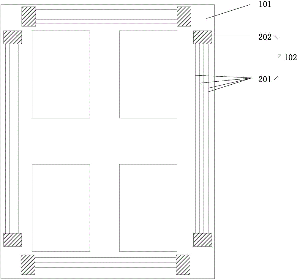
[0058] Please refer to figure 1 , figure 1 It is a schematic structural diagram of the substrate according to Embodiment 1 of the present invention, and the substrate includes: a base substrate 101 and four edge-grinding detection patterns 102 arranged on the base substrate 101, and the four edge-grinding detection patterns 102 are respectively Set on the four edges of the base substrate 101, the edge grinding detection pattern 102 is made of conductive material.

[0059] In the embodiment of the present invention, each of the edge grinding detection patterns 102 includes a plurality of resistance lines 201 arranged side by side, and the extension direction of the resistance lines 201 is the same as the extension direction of the edge of the base substrate 101 on which the resistance lines 201 are located.

[0060]Preferably, the multiple resistance lines 201 have the same width. Further preferably, the intervals between adjacent resistance lines 201 are the same.

[0061] ...

Embodiment 2

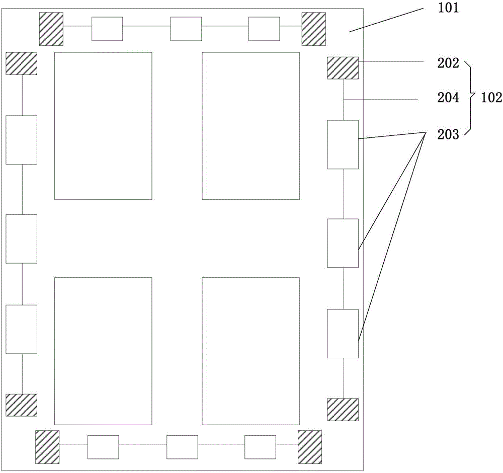
[0070] Please refer to figure 2 , figure 2 It is a schematic structural diagram of the substrate according to Embodiment 2 of the present invention, and the substrate includes: a base substrate 101 and four edge-grinding detection patterns 102 arranged on the base substrate 101, and the four edge-grinding detection patterns 102 are respectively Set on the four edges of the base substrate 101, the edge grinding detection pattern 102 is made of conductive material.

[0071] In the embodiment of the present invention, each of the edge grinding detection patterns 102 includes a plurality of resistance blocks 203 and a plurality of connecting wires 204 for connecting the plurality of resistance blocks 203 in series.

[0072] Preferably, the multiple resistor blocks 203 have the same size, and the multiple resistor blocks 203 are aligned along the extending direction of the edge of the base substrate 101 where they are located.

[0073] After the substrate of the embodiment of t...

Embodiment 3

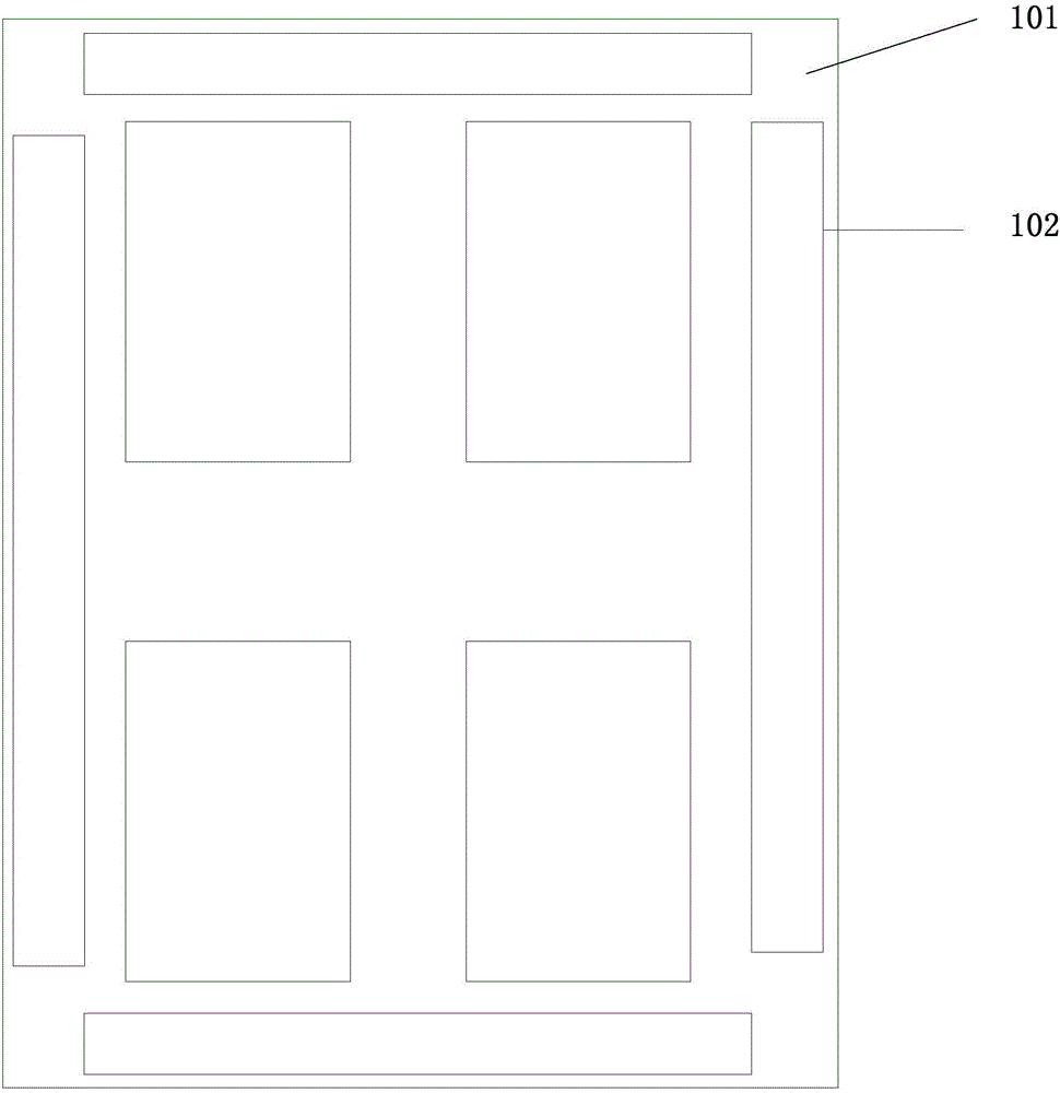
[0080] Please refer to image 3 , image 3 It is a schematic structural diagram of the substrate according to Embodiment 3 of the present invention, and the substrate includes: a base substrate 101 and four edge-grinding detection patterns 102 arranged on the base substrate 101, and the four edge-grinding detection patterns 102 are respectively Set on the four edges of the base substrate 101, the edge grinding detection pattern 102 is made of conductive material. In the embodiment of the present invention, the edge grinding detection pattern 102 is a strip-shaped conductive pattern, and the extending direction of the long side of the strip-shaped conductive pattern is the same as the extending direction of the edge of the substrate on which it is located.

[0081] After the substrate of the embodiment of the present invention is edged, since the edge grinding detection pattern 102 is close to the edge of the substrate, each strip-shaped edge grinding detection pattern 102 may...


PUM


Abstract

The invention provides a base plate and an edging detection method, alignment method and device thereof. The base plate comprises a substrate base plate body and at least one edging detection figure arranged on the substrate base plate body. The edging detection figure is arranged at the edge of the substrate base plate body and made of electrically conductive materials. Due to the fact that the edging detection figure is arranged at the edge of the substrate base plate body and made of the electrically conductive materials, after the base plate is subjected to edge grinding, the abrasion degree of the edging detection figure can be determined by detecting the resistance of the edging detection figure, and thus the abrasion degree of the base plate is determined. Compared with the prior art, the edge grinding detection method is more accurate, an implement method is simple, and the cost is low.

Description

technical field [0001] The invention relates to the field of display technology, in particular to a substrate and its edge grinding detection method, alignment method and device. Background technique [0002] When the size of the glass substrate used to make the display device is large and does not match the size required by the equipment in the subsequent process, the glass substrate needs to be cut first. After the glass substrate is cut, there will be more burrs on the edge. The glass substrate is edged to prevent damage to the glass in subsequent processes. [0003] In the existing technology, the effect of edging the glass substrate is often judged by experienced engineers with the naked eye, so there is a large error, which will cause great difficulties in the alignment of the subsequent process, occupy the machine table, and waste machine time , reducing production efficiency. Contents of the invention [0004] In view of this, the present invention provides a sub...

Claims


Application Information

Patent Timeline
Patent Type & Authority Applications(China)
IPC IPC(8): B24B9/10B24B49/10B24B49/04G01D21/00
CPCB24B9/10B24B49/04B24B49/10G01D21/00B24B21/02
Inventor 王强刘利宾
Owner BOE TECH GRP CO LTD
Why Eureka
Try Eureka