Locating and conveying cutting equipment of eraser strip
A technology of cutting equipment and rubber strips, applied in metal processing and other directions, can solve the problems of easy dislocation of patterns, difficult removal of rubber blocks, easy fading, etc., to achieve the effect of improving production efficiency
- Summary
- Abstract
- Description
- Claims
- Application Information
AI Technical Summary
Problems solved by technology
Method used
Image
Examples
Embodiment 1
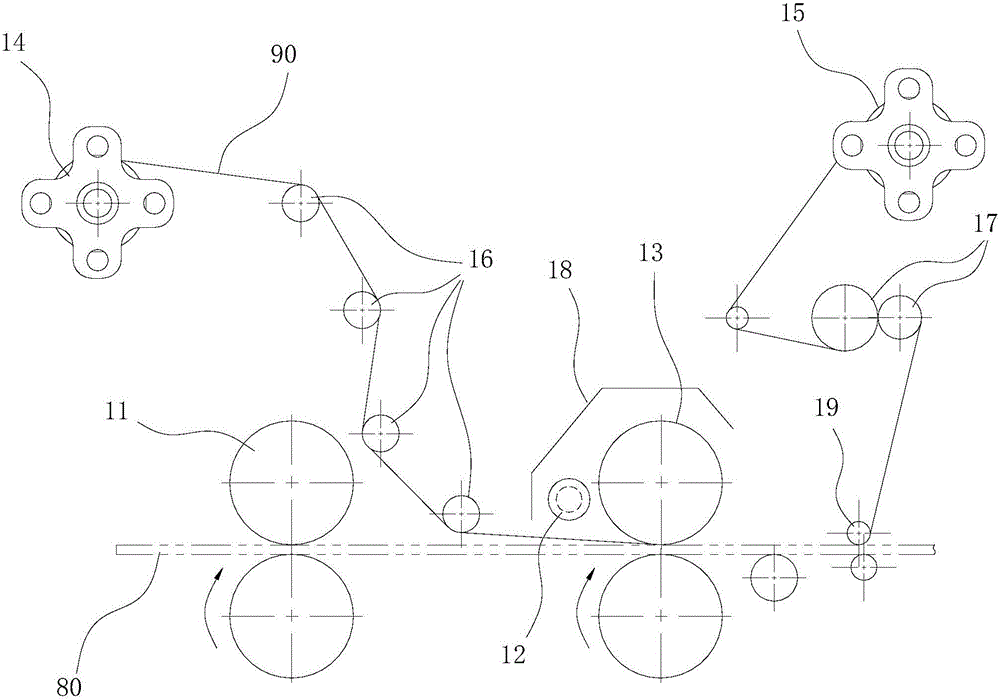
[0014] The pattern pasting device comprises the first conveying roller 11, the heating unit 12 and the pressure roller 13 arranged in sequence, the first conveying roller 11 is used to convey the flat rubber strip 80 and feeds forward, and the heating unit 12 is used to heat the sticker 90 with the pattern , the pressing roller 13 is used to press the sticker 90 and the flat rubber strip 80 so that the pattern is pasted on the flat rubber strip 80 . In the present invention, the sticker 90 is first heated to increase the adhesiveness of the sticker pattern, so that the pattern and the rubber are firmly pasted.
[0015] Further, the pattern pasting device also includes an unwinding roller 14 and a winding roller 15; the sticker 90 with a pattern is wound on the unwinding roller 14, and the sticker 90 passes through the heating area of the heating unit 12, and is then combined with the flat rubber The strip 80 sticks and passes through the pressing roller 13, and then separate...
Embodiment 2
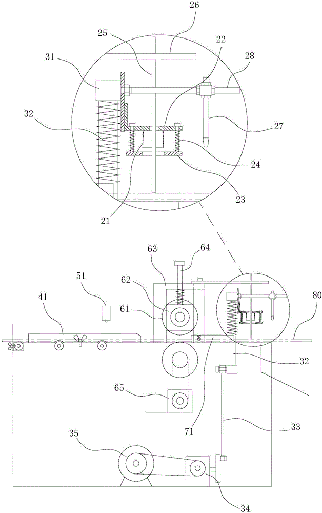
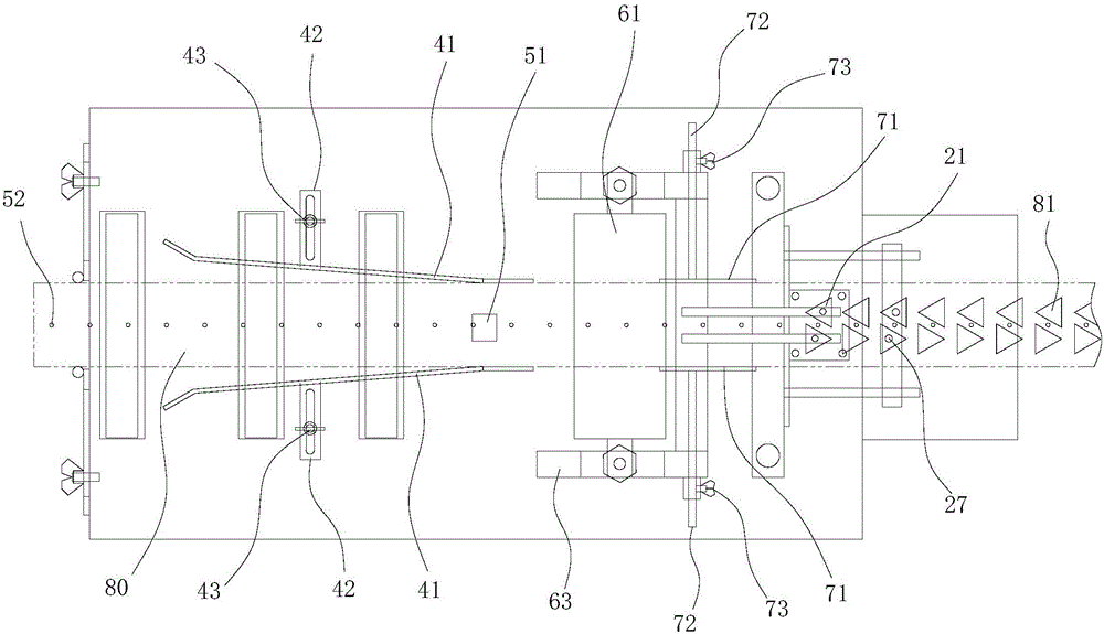
[0021] The stamping device includes a stamping die and an intermittent feeding mechanism; the stamping die includes a cylindrical cutter 21, and the cylindrical cutter 21 reciprocates along the vertical direction for punching out a rubber block 81 on a flat rubber strip 80; the intermittent feed The feeding mechanism is used to convey the flat rubber strip 80 intermittently to the bottom of the stamping die, specifically: when the cylindrical cutter 21 is lifted, the flat rubber strip 80 is fed forward; when the cylindrical cutter 21 falls, the flat rubber strip 80 stops advancing. Give. The cross-sectional shape of the cylindrical cutter 21 can be adjusted according to production requirements, and can be a triangle, a star, a circle or a shape similar to the outline of a cartoon pattern.
[0022] Preferably, the cylindrical cutter 21 is installed on the cutter fixing plate 22, and a binder plate 23 is arranged below the cutter fixing plate 22, and the binder plate 23 forms a ...
Embodiment 3
[0028] The introduction device is located at the front end of the intermittent feeding mechanism, that is, the end where the flat rubber strip 80 enters. The introduction device includes two strip-shaped plates 41, and the two strip-shaped plates 41 are roughly arranged in a figure-eight shape when viewed vertically. , the gap between the two strip-shaped plates 41 constitutes the passage through which the flat rubber strip 80 passes, the passage is set up against the intermittent feed mechanism, and the wider end of the passage is far away from the intermittent feed mechanism, and the narrower end is far away from the intermittent feed mechanism. One end is set close to the intermittent feeding mechanism. The introduction device can guide the flat rubber strips 80 to advance along the center line of the equipment, preventing the flat rubber strips 80 from shifting during conveyance.
[0029] Further, the distance between the two strip-shaped plates 41 of the introduction devi...
PUM
 Abstract
Description
Claims
Application Information
 - R&D
- Intellectual Property
- Life Sciences
- Materials
- Tech Scout
- Unparalleled Data Quality
- Higher Quality Content
- 60% Fewer Hallucinations
Browse by: Latest US Patents, China's latest patents, Technical Efficacy Thesaurus, Application Domain, Technology Topic, Popular Technical Reports.
© 2025 PatSnap. All rights reserved.Legal|Privacy policy|Modern Slavery Act Transparency Statement|Sitemap|About US| Contact US: help@patsnap.com


