Front section for motor vehicle

A technology of a car, arm, applied in the field of the front of the car

Inactive Publication Date: 2016-10-26
GM GLOBAL TECH OPERATIONS LLC
View PDF5 Cites 1 Cited by
  • Summary
  • Abstract
  • Description
  • Claims
  • Application Information

AI Technical Summary

Problems solved by technology

[0003] Although it is conceivable to adjust the width of the bumper beam to the width of the bumper skin, this result

Method used


Image

  • Front section for motor vehicle
  • Front section for motor vehicle
  • Front section for motor vehicle

Examples


Embodiment Construction

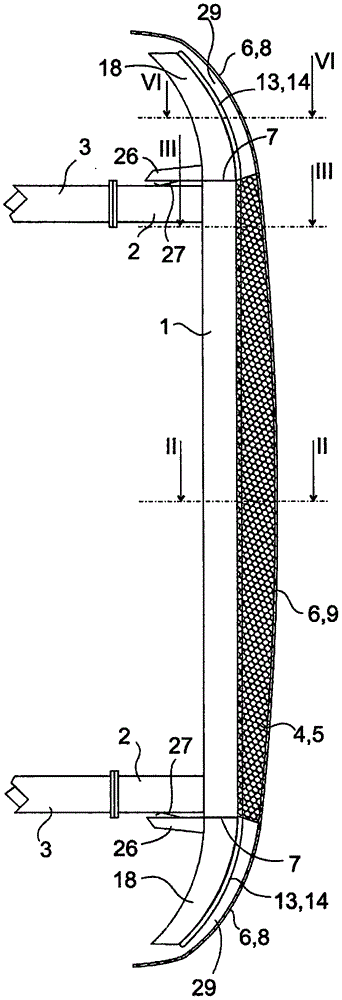
[0029] figure 1 Shown is a plan view of a bumper cross member 1 which is fastened in a known manner via two rear-mounted crash boxes 2 to a side member 3 which extends substantially over the entire length of the motor vehicle and forms the basic structure of its body. supporting components. The bumper beam 1 and the crash box 2 are hollow profiles made of metal, the load capacity of which is set sufficiently that in the event of a collision with another vehicle or other object of similar weight, it absorbs the impact energy and is thereby deformed, And thus protect the side member 3 against deformation in the event of a low-energy impact.

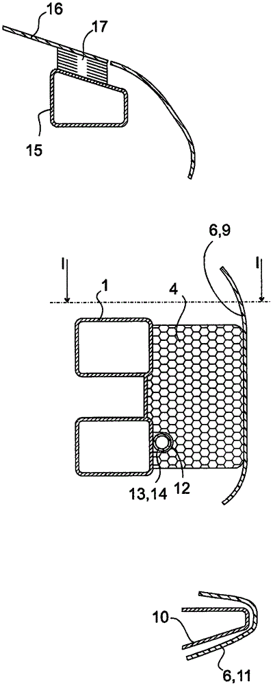
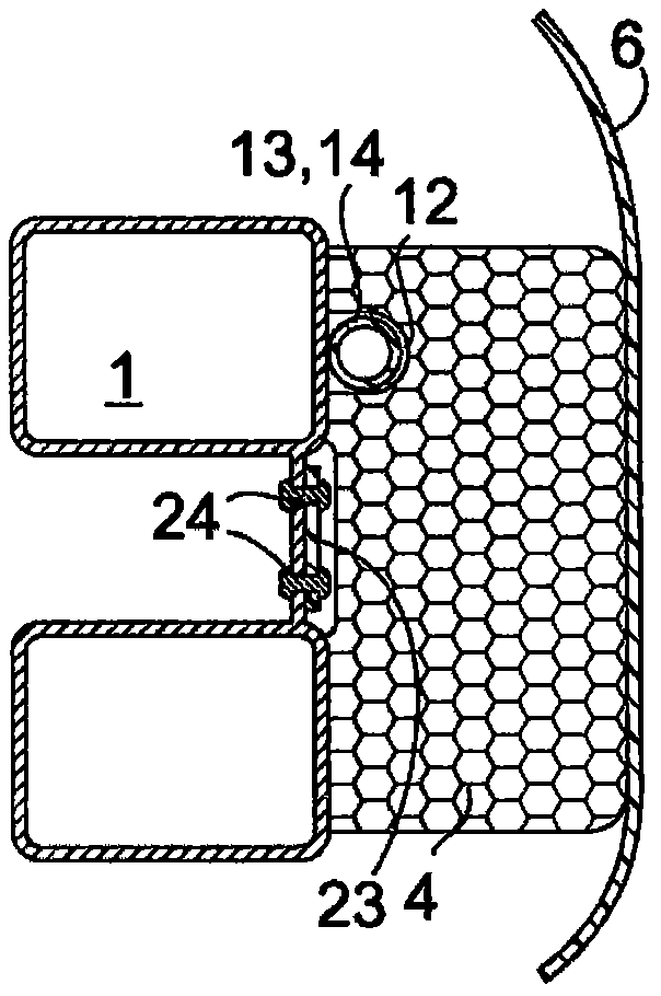
[0030] The energy absorber 4 fills the gap 5 between the bumper beam 1 and the bumper skin 6 . The energy absorber 4 can, for example, be a molded body made of rigid foam or a thin-walled injection molding, in particular with a honeycomb structure. The mechanical resistance of the energy absorber 4 and the bumper skin 6 is significantly ...


PUM


Abstract

A front section of a motor vehicle includes a bumper shell (6), a bumper cross member and a shock sensor arranged at various locations inside a central intermediate space between the bumper shell and the bumper cross member. The bumper shell extends beyond the ends of the bumper cross member in the direction transverse to the vehicle. Extensions are attached to the ends of the bumper cross member, and the shock sensor is also distributed in various locations in peripheral intermediate spaces between the extensions and the bumper shell.

Description

technical field [0001] The invention relates to the front of a motor vehicle in which impact sensors are arranged locally dispersed in the gap between a bumper beam and a bumper skin in order to detect a collision between the bumper skin and a pedestrian. German patent document DE 10 2010 022 686 A1 describes such a vehicle front and proposes to use the detection signal (Erfassungssignal) from its impact sensor for activating the pedestrian protection device, which is not further described in the above-mentioned document . Background technique [0002] In conventional vehicle fronts, the width of the bumper beam is significantly smaller than the width of the bumper skin. If the central area of ​​the bumper skin hits an external object and deforms after contact with it, this is reliably detected by the pressure sensor. The side area of ​​the bumper skin, which is opposite the end of the bumper beam, can in principle be deformed at will, but cannot be detected by the impact ...

Claims


Application Information

Patent Timeline
IPC IPC(8): B60R19/18B60R19/48
CPCB60R19/18B60R19/483B60R2019/1866B60R2019/1806B60R21/01B60R2019/186
Inventor M·尼克尔M·利卡
Owner GM GLOBAL TECH OPERATIONS LLC
Why Eureka
Try Eureka