High speed multi-head annealing machine

An annealing, multi-head technology, applied in furnaces, heat treatment equipment, heat treatment furnaces, etc., can solve the problems of long annealing and cooling process, low production efficiency, and different wire diameters cannot provide annealing treatment process.

Inactive Publication Date: 2016-10-26
JIANGSU HONTA MACHINERY
View PDF5 Cites 4 Cited by
  • Summary
  • Abstract
  • Description
  • Claims
  • Application Information

AI Technical Summary

Problems solved by technology

There are many annealing methods after wire drawing. The traditional annealing method is to anneal the drawn wire separately. This method has low production efficiency and occupies a large space. Its application has gradually decreased and has been replaced by continuous on-line annealing. The DC continuous resistance annealing method is a common form of the online annealing method. It uses the principle of generating heat after the current passes through the wire to heat the wire during the running process after drawing to achieve annealing treatment. Its production efficiency is relatively high. The annealing process can be combined with the wire drawing equipment for continuous production, and the site occupation is relatively small, but the conventional annealing equipment of this type has a long annealing and cooling process, and it needs to go through a long distance for drying treatment, and the wire is easy to heat up after heating. It reacts with air to produce oxidation, the quality of the annealed wire is difficult to guarantee, and the efficiency is not high. In addition, the adaptability of the equipment is not strong, and it is not possible to provide differentiated annealing processes for different wire diameters.

Method used


Image

  • High speed multi-head annealing machine
  • High speed multi-head annealing machine
  • High speed multi-head annealing machine

Examples


Embodiment Construction

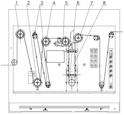
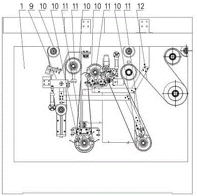
[0027] exist figure 1 with figure 2In the high-speed multi-head annealing machine shown, the frame 1 is a wallboard-type metal member, and the wallboard of the wallboard-type frame 1 is vertically arranged. The wallboard has two working surfaces, the front and the back, and there are rectangular Frame, the rectangular frame and the front and back working surfaces of the wallboard form the structural space on the front and back sides of the frame 1, and the multiple wires to be annealed after being drawn by the wire drawing machine are rotated from one side of the frame around the wallboard The driving guide wheel supported on the frame 1 enters the structural space on one side of the frame 1 for annealing treatment. The driving guide wheel is fixedly connected to one end of its installation shaft, and the installation shaft passes through the wall plate through the installation shaft seat and is rotatably supported on the On the frame 1, a transmission wheel is fixedly conne...


PUM


Abstract

The present invention discloses a high speed multi-head annealing machine, which comprises a rack, an annealing section positive electrode guide wheel, an annealing section negative electrode guide wheel, an annealing section output guide wheel and a preheating section guide wheel, wherein the annealing section positive electrode guide wheel, the annealing section negative electrode guide wheel, the annealing section output guide wheel and the preheating section guide wheel are rotatablely supported on the rack, the annealing section positive electrode guide wheel, the annealing section negative electrode guide wheel, the annealing section output guide wheel and the preheating section guide wheel are electrically connected to an annealing electricity transmission device having a sectioning and switching function, the annealing section positive electrode guide wheel, the annealing section negative electrode guide wheel, the annealing section output guide wheel, the preheating section guide wheel and a drive device form transmission connection, and an annealing drying device integrating functions of protection, cooling and drying is arranged on the rack, and is positioned at the wire path between the annealing section positive electrode guide wheel and the annealing section output guide wheel. According to the present invention, the high speed multi-head annealing machine has characteristics of high annealing treatment efficiency, compact structure, high wire quality, and strong process adaptability.

Description

technical field [0001] The invention relates to wire production equipment, in particular to annealing equipment after wire drawing. Background technique [0002] In the production process of wire rods, thicker wire rods are drawn into thinner wire rods through the wire drawing process, that is, the thicker wire rods are drawn through the wire drawing die to produce plastic deformation and become thinner wire rods, and the wire rods are processed by cold drawing In the future, there will be a hardening phenomenon, and the tensile strength and yield strength will increase significantly, which will have a great impact on the use or further processing of the wire. In order to restore the physical and mechanical properties before cold working and eliminate internal stress and defects, annealing treatment is necessary. There are many annealing methods after wire drawing. The traditional annealing method is to anneal the drawn wire separately. This method has low production effici...

Claims


Application Information

Patent Timeline
IPC IPC(8): C21D9/52C21D1/26
CPCC21D9/525C21D1/26
Inventor 谭礼春
Owner JIANGSU HONTA MACHINERY
Why Eureka
Try Eureka