Widening processing structure of prefabricated channel steel of prefabricated erected simply-supported beam between tunnels and construction method thereof
A technology of simply supported beams and steel structures, which is applied in the erection/assembly of bridges, bridges, bridge construction, etc., which can solve the problems of long construction period for on-site pouring, difficulty in placing materials and construction machines and tools, etc., to simplify on-site construction procedures and shorten The effect of construction period and convenient construction
- Summary
- Abstract
- Description
- Claims
- Application Information
AI Technical Summary
Problems solved by technology
Method used
Image

Examples
Embodiment Construction
[0027] The present invention will be described in detail below in combination with specific embodiments.
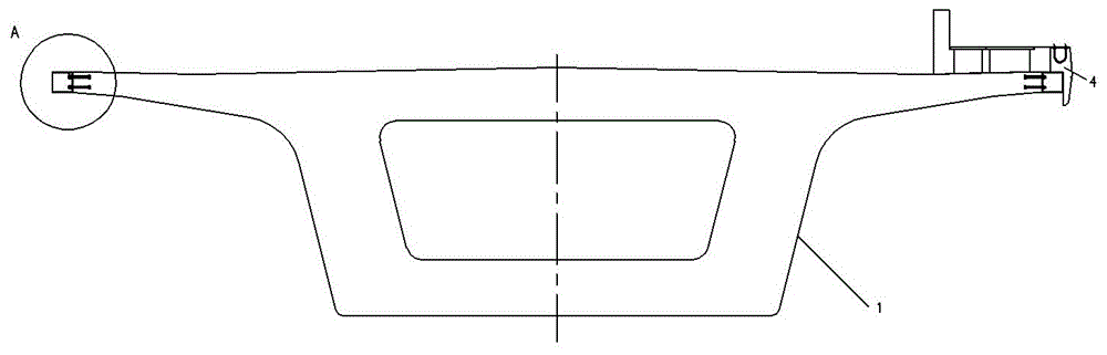
[0028] The present invention relates to a prefabricated and erected simply supported beam prefabricated channel steel widening structure between tunnels, which can be prefabricated and preassembled in the beam yard, and can be disassembled and transported in place by a beam transport vehicle or an integrated machine for transport and frame erection. Connect and pour the later cast-in-place vertical walls, etc. It can greatly simplify the on-site construction process and effectively shorten the construction period, and has obvious economic benefits.
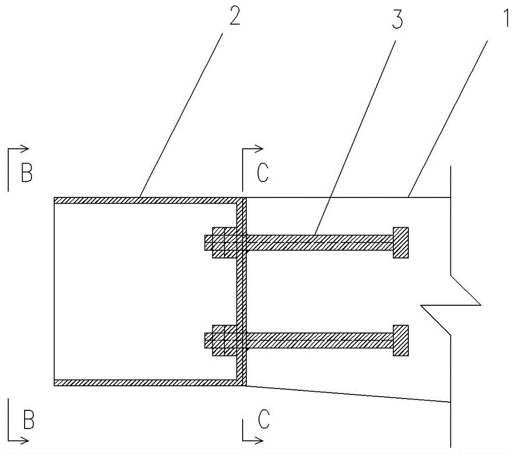
[0029] The present invention makes the prefabricated box girder 1 transition from the original standard beam width of 12.6m to the prefabricated box girder beam width of 12.1m, and the prefabricated channel steel member 2 is arranged outside the flange end face of the prefabricated box girder 1, and the prefabricated channel ...
PUM
 Abstract
Description
Claims
Application Information
PatSnap Eureka turns technology decisions into work you can execute. Powered by our Innovation Knowledge Graph, it runs expert workflows across engineering, life sciences, materials and intellectual property. Get your review-ready output in minutes.


