Method and device for forming wall through rolling groove

A roller trough and wall-forming technology, which is applied to sheet pile walls, earth movers/excavators, construction, etc., can solve problems such as difficult control of the quality of consolidated bodies, troubles for engineering designers, and strong ground adaptability, etc., to achieve Excellent performance, novel structure, and strong stratum adaptability

Active Publication Date: 2016-10-26
CHINA WATER NORTHEASTERN INVESTIGATION DESIGN & RES
View PDF6 Cites 2 Cited by
  • Summary
  • Abstract
  • Description
  • Claims
  • Application Information

AI Technical Summary

Problems solved by technology

The groove drilling method has strong adaptability to the formation, but the process is complicated, the work efficiency is low, and the cost is high
[0006] Mixing method (including single-head drill and multi-head drill), using the power head drill to drive the propeller or vane drill bit through the drill pipe to drill into the formation, and at the same time inject cement slurry to mix with the formation particles, and form a consolidated body after solidification to strengthen the formation. For anti-seepage engineering, its anti-seepage performance is poor
The stirring method is relatively simple, but it has poor adaptability to the formation, low work efficiency, and difficult to control the quality of the consolidated body
[0007] Although there are many methods for constructing underground diaphragm walls in geotechnical engineering fields such as water conservancy and hydropower, there has been a lack of a simple construction method with strong stratum adaptability, high efficiency, high quality and low cost, which has caused great trouble to engineering designers.

Method used


Image

  • Method and device for forming wall through rolling groove
  • Method and device for forming wall through rolling groove

Examples


Embodiment Construction

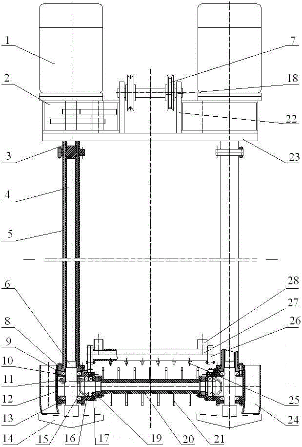
[0030] The structure of the roller groove wall forming device is: the drilling tool system on both sides is fixedly connected with the lifting device, the two ends of the bottom roller system are respectively connected with the drilling tool system, and the flushing pipe assembly is arranged on the upper part of the roller;

[0031] The structure of the drilling tool system is: the motor 1 is connected to the drill pipe 4 through the output shaft 3 of the reduction box 2, the outer tube 5 is located outside the drill pipe 4, the upper end of the transmission shaft 6 is connected to the drill pipe 4, and the lower end is connected to the drill bit 14 , the bearing seat 9 is fixedly connected to the housing 12, the transmission shaft 6 is rotationally connected to the bearing 10, the gear 11 is fixedly connected to the transmission shaft 6, and the upper cover 8 and the lower cover 13 are respectively connected to the housing;

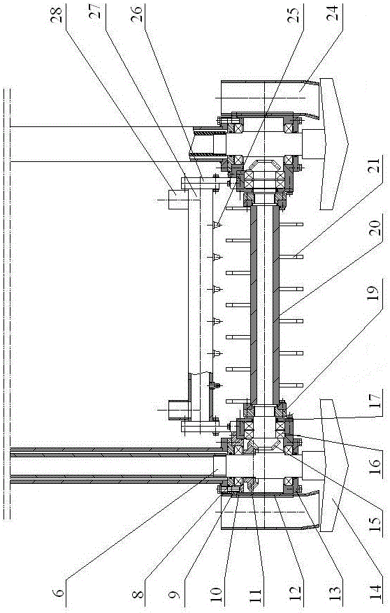
[0032] The structure of the bottom roller system is...


PUM


Abstract

The invention relates to a method and a device for forming a wall through rolling a groove, belongs to an all-new construction method and special equipment for constructing an underground diaphragm wall, and belongs to the field of water conservancy hydropower and the field of geotechnical engineering. Drilling systems on two sides are separately and fixedly connected with a lifting device; two ends of a roller system at the bottom are separately connected with the corresponding drilling system; a flushing pipe assembly is arranged on a roller. The method comprises the following steps that a groove is formed in a stratum through surface milling to form a groove segment; materials including cement grout and the like can be directly injected into the groove section; the injected materials are stirred and mixed with stratum particles; solidification is performed on the stirred and mixed materials to form the wall. According to the method disclosed by the invention, a slurry dado can also be adopted and is replaced by materials including concrete and the like, or a geomembrane is arranged, so that an underground diaphragm wall or an impermeable barrier is built. The method and the device disclosed by the invention is suitable for various of soil layers, sand layers, gravel stone layers and strong-weathering rock strata; the stratum particles are cut and peeled off through surface milling, and groove holes can be formed in the slurry dado, and then the slurry is replaced by the materials for forming the wall, so that the wall is formed; and a self-solidifying type grout can also be used for stirring into the strata to form the underground diaphragm wall directly.

Description

technical field [0001] The invention belongs to a new construction method and special equipment for building an underground diaphragm wall in the fields of water conservancy, hydropower and geotechnical engineering. It is mainly used to form slot holes in the stratum by roller milling, and a diaphragm wall can be built. It is widely used in underground load-bearing of buildings and underground anti-seepage of hydraulic structures, and the market prospect is very broad. Background technique [0002] The commonly used underground diaphragm wall construction methods mainly include the grab method, the sawing method, the drilling method and the mixing method. [0003] Grab method (including hydraulic grab and mechanical grab), crawler cranes are used to lift grab equipment to grab the ground to form a groove section, use mud to protect the wall, and then use concrete and other materials to replace the mud to build a continuous wall. The grab method has strong adaptability to th...

Claims


Application Information

Patent Timeline
Patent Type & Authority Applications(China)
IPC IPC(8): E02F5/02E02D5/18
CPCE02D5/187E02F5/02
Inventor 孙灵会
Owner CHINA WATER NORTHEASTERN INVESTIGATION DESIGN & RES
Why Eureka
Try Eureka