
A built-in segmented steel plate-high-strength concrete composite shear wall and its construction method

A combined shear wall and concrete technology, applied in building structures, walls, buildings, etc., can solve problems such as increasing the stiffness of the shear wall, affecting the overall stress of the steel plate and concrete, and reducing the cooperative work performance of the shear wall.

Active Publication Date: 2018-11-13
TONGJI UNIV
View PDF5 Cites 0 Cited by
  • Summary
  • Abstract
  • Description
  • Claims
  • Application Information

AI Technical Summary

Problems solved by technology

[0005] The traditional built-in steel plate-concrete composite shear wall often uses a whole steel plate. When the steel plate is not opened, the tie bars cannot connect the distribution bars on both sides of the steel plate, which makes the connection form complicated, and sometimes even affects the overall strength of the steel plate and concrete. The opening of the steel plate increases the workload and weakens the steel plate. The tie bars may not be able to connect and distribute the bars smoothly, which brings great difficulty to the construction; the whole steel plate separates the concrete of the shear wall, which affects the concrete. Pouring reduces the overall cooperative performance of the shear wall; more importantly, the use of the whole steel plate will greatly increase the stiffness of the shear wall. During the transition between floors, the stiffness transition is not easy to control, which in turn will affect the seismic performance of the structure

Method used


Image

  • A built-in segmented steel plate-high-strength concrete composite shear wall and its construction method
  • A built-in segmented steel plate-high-strength concrete composite shear wall and its construction method
  • A built-in segmented steel plate-high-strength concrete composite shear wall and its construction method

Examples


Embodiment 1

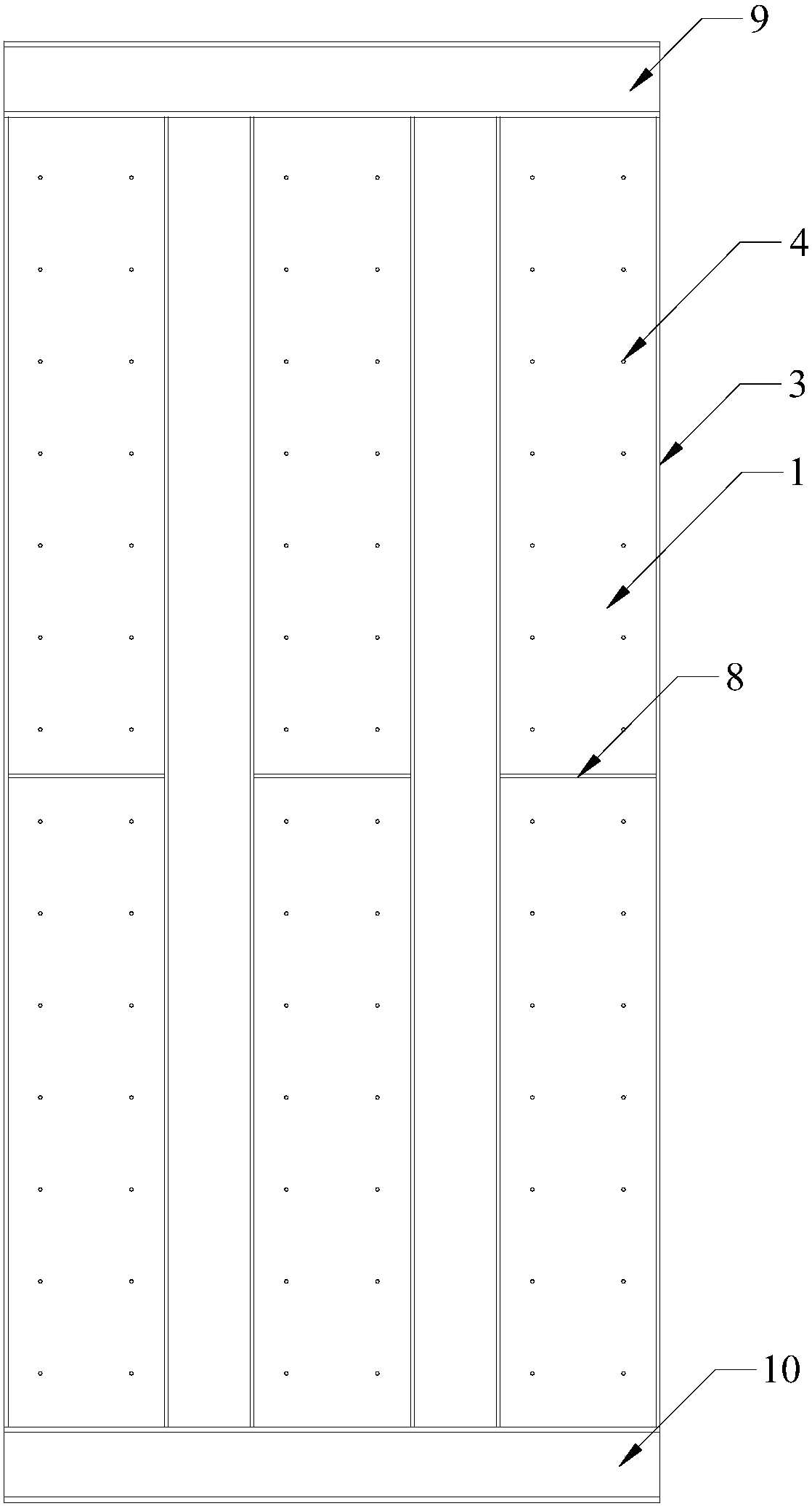
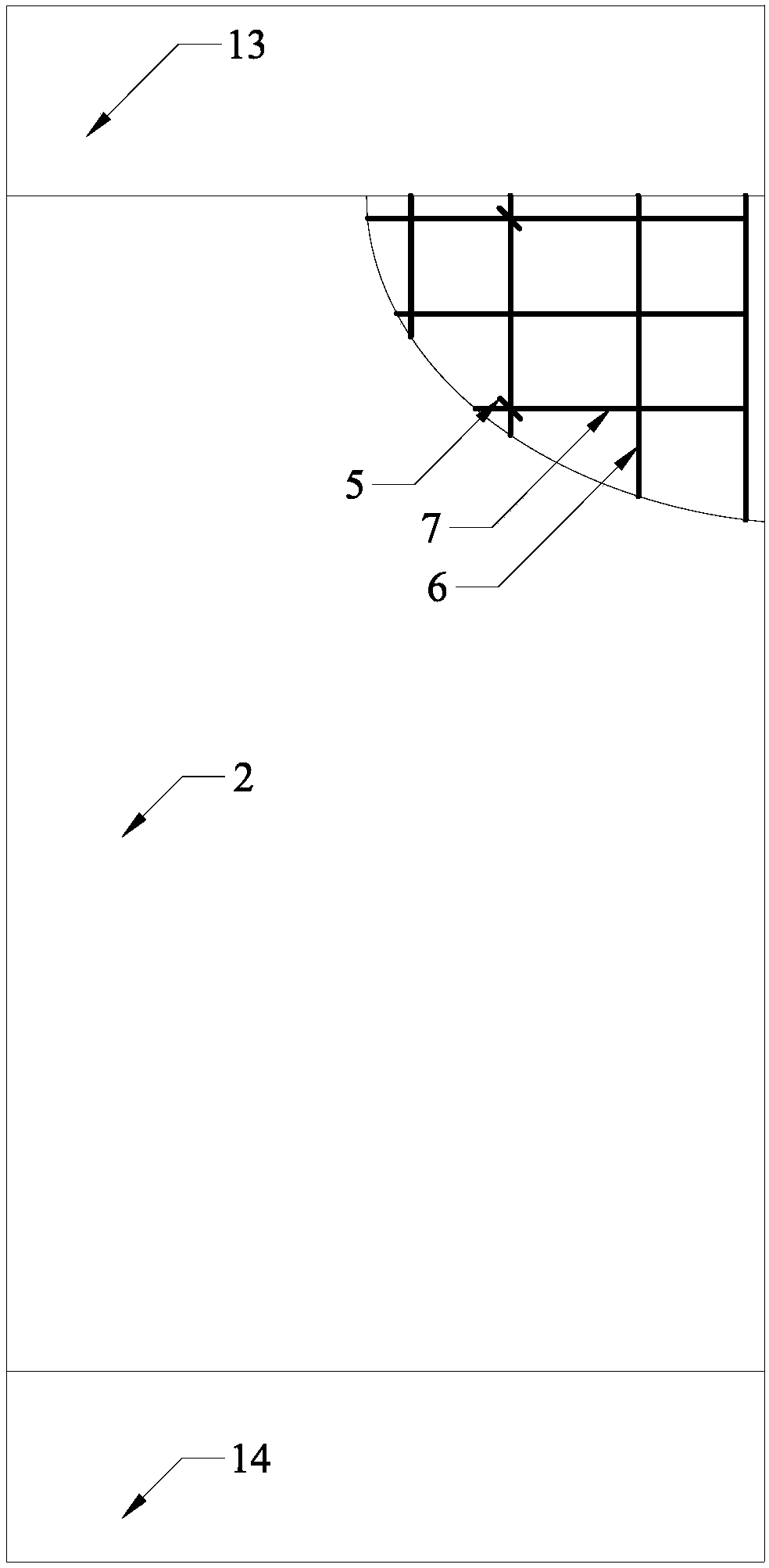
[0152] Through the model test, the similarity ratio is selected as 1 / 3, and two combined shear walls are designed and tested. Take 3 segmented steel plate sections, all of which are 3mm×172mm in size, and the gap distance between the segmented steel plate sections is 100mm. Stiffeners and studs are welded on each segmented steel plate section, the stiffeners include horizontal stiffeners and vertical stiffeners, horizontal stiffeners and vertical stiffeners are arranged in pairs, horizontal stiffeners and vertical stiffeners The ribs surround the outer sides of the segmented steel plates. The size of the vertical stiffener is 4mm×40mm, the size of the horizontal stiffener is 4mm×20mm, the spacing is 500mm, and the slenderness ratio of the steel plate between the stiffeners is 70. The studs are welded to the side of the steel section where the horizontal stiffeners are located. The horizontal spacing between the studs is 100mm, the vertical spacing is 100mm, the size of the s...


PUM

PropertyMeasurementUnit
particle sizeaaaaaaaaaa

Abstract

The invention belongs to the technical field of structure engineering and relates to a high-strength concrete composite shear wall with built-in segmented steel plates and a construction method for the same. The invention provides the high-strength concrete composite shear wall with the built-in segmented steel plates and further provides the building and construction method for the shear wall. The composite shear wall and the construction method for the same provided by the invention are characterized in that through segmented layout of the steel plate, concrete pouring and binding bar layout become convenient; a cooperative working ability of the steel plates and concrete is enhanced; bearing force is ensured; and deformability and an energy-dissipation capability of the composite shear wall can also be enhanced. In comparison with a composite shear wall covered by steel plates, the composite shear wall provided by the invention has higher resistance to high temperatures and can show better performance when a fire disaster takes place. Meanwhile, in comparison with a concrete composite shear wall with a whole steel plate, the shear wall provided by the invention has the advantages that conversion and transition among layers can be implemented through reduction of the quantity of the segmented steel plates; inter-layer rigidity transition becomes gentler; and the structure is also simpler.

Description

technical field [0001] The invention belongs to the technical field of structural engineering, and relates to a built-in segmented steel plate-high-strength concrete composite shear wall and a construction method thereof. Background technique [0002] With the development and progress of structural design level and construction technology, the height records of high-rise buildings are constantly being refreshed, and the requirements for the lateral force resistance of building structures are also getting higher and higher. As an important anti-lateral component, shear wall is widely used in high-rise and super high-rise buildings. [0003] Due to the high height and self-heaviness of high-rise buildings, the shear walls need to bear a considerable vertical load while bearing the horizontal load. The traditional reinforced concrete shear wall needs to increase its cross-sectional area to meet the requirements, but at the same time it will reduce the building area. The compo...

Claims


Application Information

Patent Timeline
Patent Type & Authority Patents(China)
IPC IPC(8): E04B2/56
CPCE04B2/56
Inventor 肖建庄谢青海谢文刚柳献
Owner TONGJI UNIV
Learn More