Furnace top seal device

A sealing device and furnace roof technology, which is applied in the combustion method, combustion chamber, outer cover/lining, etc., can solve the problems of huge thermal alternating stress and maintain the validity period of 1-3 years, so as to avoid cracking and prolong the service life. Effect

Inactive Publication Date: 2016-10-26
江苏兴鼎力炉窑工程有限公司
View PDF0 Cites 1 Cited by
  • Summary
  • Abstract
  • Description
  • Claims
  • Application Information

AI Technical Summary

Problems solved by technology

This process cannot effectively solve the problem of air leakage and ash leakage caused by the thermal expansion of the furnace body during the normal operation of the boiler.
Because in principle, different heating surfaces of boilers have different pipe materials and different internal medium temperatures, so there must be expansion, and the thermal alternating stress is extremely huge, and domestic sealing technology is difficult to solve this technical problem
From the actual application of traditional hard metal seals in various power plants, it can be seen that the domestic furnace roof sealing technology originally adopted cannot fundamentally solve the problem of air leakage and ash leakage caused by the expansion of the boiler body, and can only play a temporary role. , and this sealing method will bring many adverse consequences to the power plant, and the validity period can only be maintained for 1-3 years

Method used


Image

  • Furnace top seal device
  • Furnace top seal device

Examples


Embodiment Construction

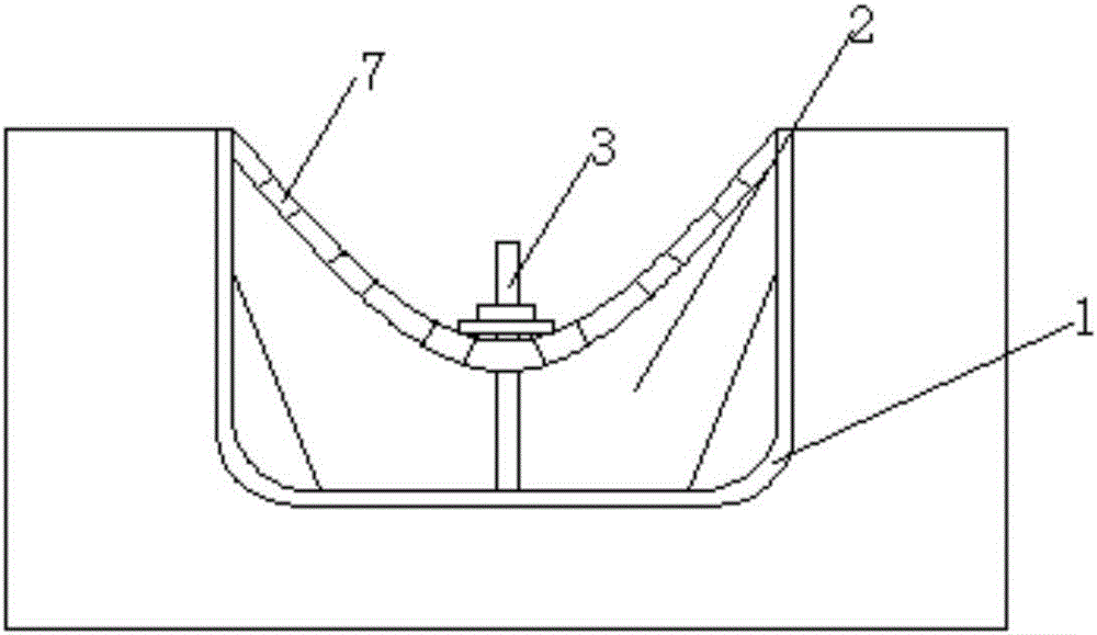
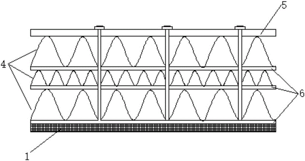
[0019] A furnace roof sealing device as shown in the accompanying drawings, includes a refractory layer 1 poured between the tube rows on the furnace roof, a plastic film leak-proof sealing layer 2 surrounded by the refractory layer 1 and welded on the furnace roof through Steel nails 3 extending from refractory layer 1 and plastic film leak-proof sealing layer 2; said refractory layer 1 includes a compacted and leveled bottom layer and an upper layer that is supplemented and repaired to realize that said refractory layer 1 is flat and smooth without cracks, and said plastic film The leak-proof sealing layer 2 is provided with three layers of ceramic fibers 4 and diamond-shaped stainless steel mesh 5 in sequence from bottom to top, and the ceramic fibers 4 are uniformly coated with high-temperature resistant adhesive 6 of uniform thickness, and the plastic film leak-proof sealing layer A layer of nickel-chromium-manganese steel soft mesh is evenly laid on the bottom layer of 2,...


PUM

PropertyMeasurementUnit
thicknessaaaaaaaaaa
thicknessaaaaaaaaaa

Abstract

The invention discloses a furnace top seal device. The device comprises a fireproof layer, a plastic film leakage-proof seal layer and a steel nail; the fireproof layer is cast between tube rows on a furnace top, the plastic film leakage-proof seal layer surrounds the fire-proof layer, and the steel nail is welded to the furnace top, penetrates the fireproof layer and the plastic film leakage-proof seal layer and extends out, and the fireproof layer comprises a compacted and leveled bottom layer and an upper layer carrying out complementing and leveling to achieve the aim that the fireproof layer is flat, smooth and free of cracks, the plastic film leakage-proof seal layer is sequentially provided with three layers of ceramic fibers and a rhombus stainless steel net from bottom to top, the positions among the ceramic fibers are evenly coated with high-temperature-resisting bonding agents with the consistent thickness, a nickel chromium manganese steel soft net is flatly laid above the bottom layer of the plastic film leakage-proof seal layer, and a fixing assembly is arranged in a manner of penetrating the steel nail and being fixed to the rhombus stainless steel net; and compared with the existing technical scheme, the furnace top seal device has the plasticity, the phenomena of cracking and air leakage caused by heat alternating stress of a boiler are effectively avoided, it is ensured that the portion of the furnace top is tight and free of leakage, and the service life of the device is greatly prolonged.

Description

technical field [0001] The invention relates to a furnace top sealing device, which belongs to the technical field of furnace top sealing. Background technique [0002] The domestic conventional roof sealing technology is to cast refractory plastic in the pre-sealed part first, fill some insulation materials, and then weld with steel plates to form a sealing layer, then use castables, and finally do insulation layer treatment. This process cannot effectively solve the problem of air leakage and ash leakage caused by the thermal expansion of the furnace body during the normal operation of the boiler. Because in principle, different heating surfaces of boilers have different pipe materials and different internal medium temperatures, so there must be expansion, and the thermal alternating stress is extremely huge, and domestic sealing technology is difficult to solve this technical problem. From the actual application of traditional hard metal seals in various power plants, it...

Claims


Application Information

Patent Timeline
Patent Type & Authority Applications(China)
IPC IPC(8): F23M5/06
CPCF23M5/06
Inventor 王兴
Owner 江苏兴鼎力炉窑工程有限公司
Why Eureka
Try Eureka