
Air conditioning system with liquid bypass device

A technology of air conditioning system and pressure relief device, which is applied in air conditioning systems, household appliances, refrigeration and liquefaction, etc., can solve the problem that the liquid bypass device cannot be accurately controlled, so as to prevent the cooling effect from deteriorating, reduce the exhaust temperature, The effect of reducing production costs and procurement costs

Inactive Publication Date: 2016-10-26
GREE ELECTRIC APPLIANCES INC
View PDF9 Cites 12 Cited by
  • Summary
  • Abstract
  • Description
  • Claims
  • Application Information

AI Technical Summary

Problems solved by technology

[0008] Therefore, the technical problem to be solved by the present invention is to overcome the defect that the liquid bypass device in the prior art cannot realize precise control, thereby providing an air conditioning system with a liquid bypass device

Method used


Image

  • Air conditioning system with liquid bypass device
  • Air conditioning system with liquid bypass device
  • Air conditioning system with liquid bypass device

Examples


no. 1 approach

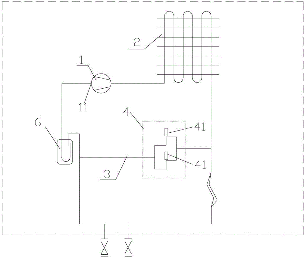
[0031] Such as image 3 As shown, the present invention provides an air conditioning system with a liquid bypass device, which includes a compressor 1 and a condenser 2, wherein the liquid bypass device includes one end connected to the outlet end of the condenser 2, and the other end connected to the The liquid bypass pipeline 3 of the suction end 11 of the compressor 1 also includes a first pressure relief device 4 arranged on the liquid bypass pipeline 3, and the first pressure relief device 4 includes more than two Pressure relief elements 41 arranged in parallel.

[0032] 1. Through the air-conditioning system with the liquid bypass device of the present invention, the liquid bypass pipeline connected between the condenser outlet and the compressor inlet can be used to relieve the high-pressure exhaust of the air-conditioning system more effectively, And reduce the exhaust temperature, and through two or more parallel pressure relief elements, the refrigerant in the liqu...

no. 2 approach

[0038] Preferably, the liquid bypass device further includes a second pressure relief device 5 arranged on the liquid bypass line 3 and connected in series with the first pressure relief device. By adopting the structural form of the second pressure relief device arranged in series with the first pressure relief device, the bypass pipeline of the air conditioning system can be further precisely adjusted and controlled on the basis of the first pressure relief device, so that this The system can better meet the requirements of high-end products for precision control (mainly pressure).

[0039] Preferably, the second pressure relief device 5 is arranged downstream of the first pressure relief device 4 in the airflow direction. This is the specific arrangement position of the second pressure relief device. Arranging it downstream of the first pressure relief device in the airflow direction can make the first pressure relief device play the role of pressure relief control first. T...


PUM


Abstract

The invention provides an air conditioning system with a liquid bypass device. The air conditioning system comprises a compressor (1) and a condenser (2). The liquid bypass device comprises a liquid bypass pipeline (3) of which one end is connected with an outlet end of the condenser (2) and the other end is connected with an air suction end (11) of the compressor (1), and further comprises a first pressure relief device (4) arranged on the liquid bypass pipeline (3), wherein the first pressure relief device (4) comprises two or more pressure relief elements (41) connected in parallel. Through the liquid bypass device, pressure of high-pressure exhaust of the air conditioning system can be relieved with greater efficiency, and the exhaust temperature is decreased; and besides, shunt pressure relief and shunt control are carried out on a refrigerant in the liquid bypass pipeline, so that the function of accurately controlling flow and pressure is achieved, and the situation that the pressure relief function cannot be achieved or the refrigeration effect becomes poor due to the fact that the bypass amount is too large to too low is effectively avoided.

Description

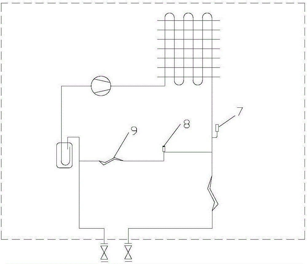
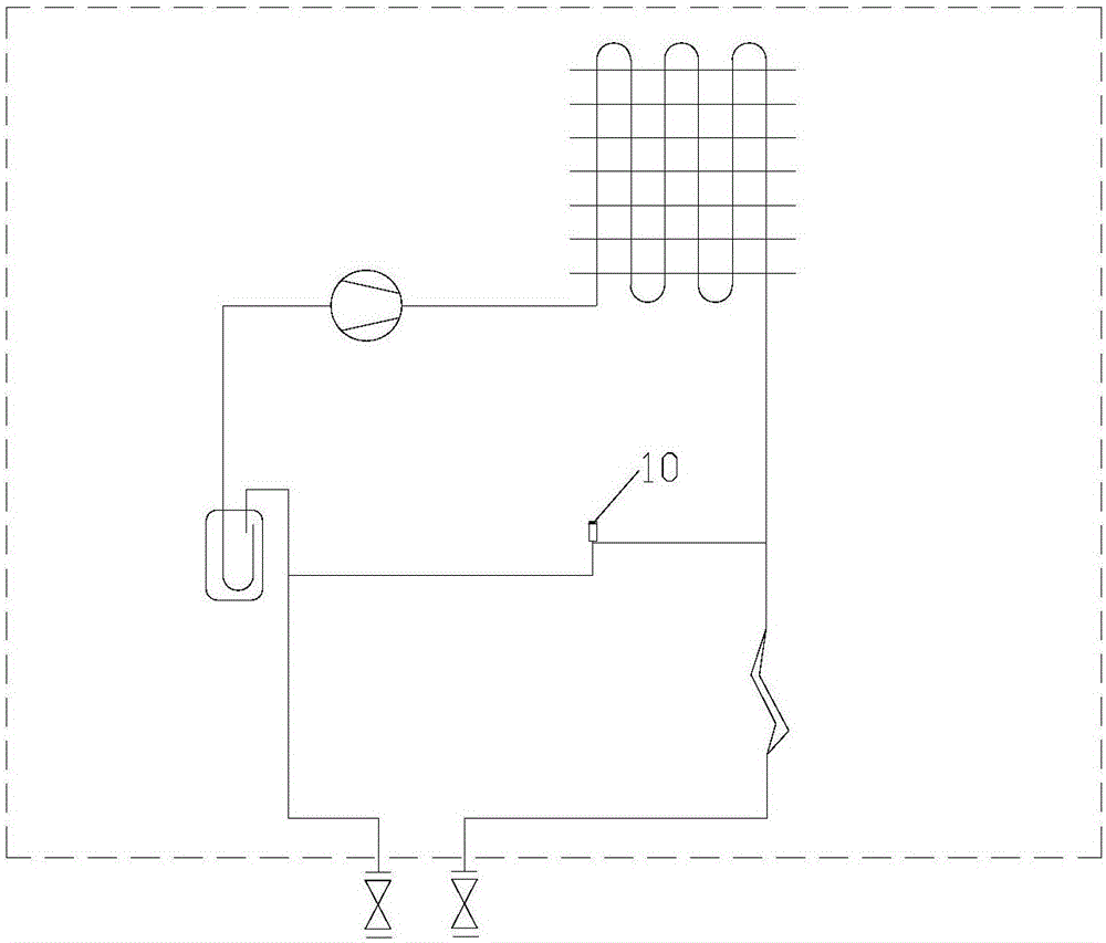
technical field [0001] The invention belongs to the technical field of refrigeration and air conditioning, and in particular relates to an air conditioning system with a liquid bypass device. Background technique [0002] The liquid bypass in the prior art means that after the refrigerant exits the condenser, part of the refrigerant enters the evaporator through a throttling device, and the other part of the refrigerant directly bypasses to the suction end of the compressor. Under high temperature load, the liquid bypass can effectively reduce the high pressure and exhaust temperature of the system, and can ensure that the unit continues to operate normally without protection shutdown while sacrificing a part of the cooling capacity. [0003] The currently used liquid bypass methods are as follows: [0004] A. Add a pressure switch or pressure sensor or temperature sensor to the pipeline system. When the pressure or temperature is higher than a certain value, open the solen...

Claims


Application Information

Patent Timeline
Patent Type & Authority Applications(China)
IPC IPC(8): F24F5/00F25B41/04F25B41/06F25B43/00F25B41/20F25B41/385F25B41/40
CPCF24F5/001F25B43/00F25B41/22F25B41/37F25B41/31
Inventor 尤文超
Owner GREE ELECTRIC APPLIANCES INC
Learn More