
An online diagnosis device and method for the status of the shafting power system of a hydraulic turbine unit

A technology of power system and diagnosis method, applied in the direction of measuring device, electric device, electromagnetic measuring device, etc., can solve the problem of inability to monitor the working state of the shafting power system, the establishment of the thickness of the lubricating water film cannot be known, and the lifting of the spindle seal ring. Insufficient height, etc., to ensure long-term safe operation, avoid heat and even wear, reduce workload and work intensity

Inactive Publication Date: 2018-08-03
STATE GRID CORP OF CHINA +3
View PDF6 Cites 0 Cited by
  • Summary
  • Abstract
  • Description
  • Claims
  • Application Information

AI Technical Summary

Problems solved by technology

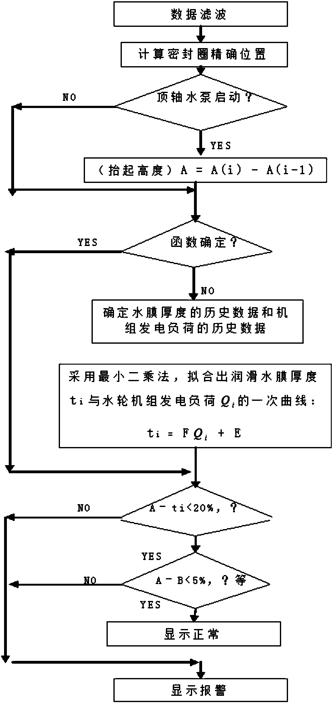
In fact, since there is no mechanical dial indicator on site during normal operation, the operator can only judge the working state of the main shaft sealing system indirectly according to the lubricating water pressure, flow rate and temperature before the turbine runs. The actual thickness of the lubricating water film The establishment situation cannot be known, which directly affects the safe operation of the unit
For example, if the cooling water pipe is partially blocked or leaks, etc., it may cause the spindle seal ring to be lifted insufficiently or the height around the lift is uneven, that is, the thickness of the lubricating water film is not enough, and the forced start will cause the spindle seal. The temperature of the sealing ring rises, causing a major accident of extrusion wear of the main shaft sealing ring
[0006] In addition, as a high-speed vertical rotating equipment, the working state of the shafting power system of the hydraulic turbine is the key factor for identifying early failures of the unit and taking timely measures to improve the operation safety of power plant equipment and the availability of the unit, while the original The equipment cannot monitor the working status of its shafting power system

Method used


Image

  • An online diagnosis device and method for the status of the shafting power system of a hydraulic turbine unit
  • An online diagnosis device and method for the status of the shafting power system of a hydraulic turbine unit

Examples


Embodiment Construction

[0044] The present invention is described in detail below in conjunction with accompanying drawing:

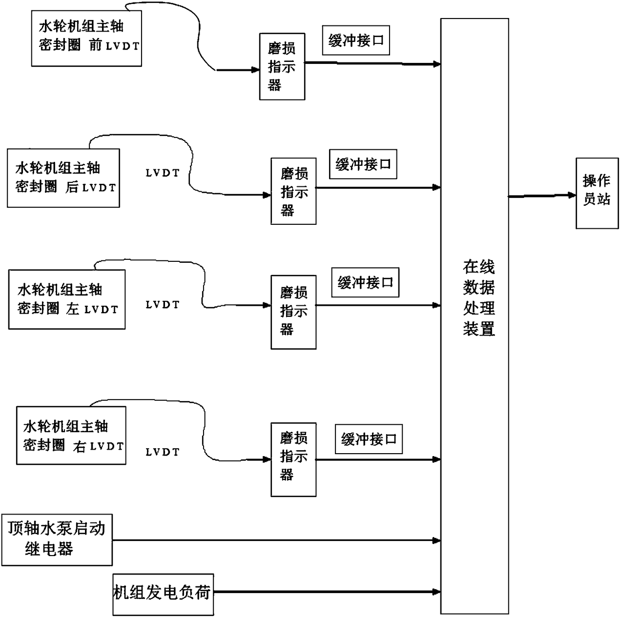
[0045] like figure 1 As shown, an online diagnostic device for the state of the shafting power system of a hydraulic turbine unit includes: a hydraulic turbine LVDT sensor, a wear indicator and an online data processing device;

[0046] LVDT sensors (differential transformers) are installed inside the turbine unit to measure the wear of the main shaft seal ring of the turbine unit; each LVDT sensor is connected to a wear indicator, and the LVDT sensor transmits the wear signal of the main shaft seal ring to the wear indicator. The wear indicator is connected to the on-line data processing device through the output buffer interface, and the on-line data processing device is connected to the operator station installed on the operating table of the central control room of the power station.

[0047] When the unit is running, the wear indicator monitors the size of the wear sign...


PUM


Abstract

The invention discloses an on-line state diagnosis device and method for a water turbine unit shafting power system. The device comprises water turbine LVDT (Linear Variable Differential Transformer) sensors, wear indicator and an on-line data processing device; a plurality of water turbine LVDT sensors are respectively arranged inside a water turbine unit, each water turbine LVDT sensor is connected with a wear indicator, and the wear indicators are connected with the on-line data processing device via output buffer interfaces. The device and the method have the advantages that the device acquires data via the buffer interfaces of a water turbine sealing ring wear indicator front panel, so that safety operation of the unit is not influenced. By using the sensors of sealing ring wear indicators, the device is low in manufacturing cost and convenient to maintain for field installation-free operation of the water turbine.

Description

technical field [0001] The invention relates to the technical field of safe operation protection and condition maintenance of a hydraulic turbine set, in particular to an online diagnosis device and method for the status of a shafting power system of a hydraulic turbine set. Background technique [0002] The pumped storage unit has the characteristics of high water head, high speed, large capacity and deep submersion depth, which determine the high performance of the main shaft seal that seals the rotating part and the fixed part of the turbine. The main shaft seal is a spring return hydrostatic pressure balanced radial double-end mechanical seal. The key point of its structure is that lubricating cooling water flows from the sealing cavity into the gap between the sealing ring and the anti-wear slip ring. [0003] After each shutdown of the turbine, when starting up again, the jacking shaft device must be opened first, and its function is to send high-pressure lubricating ...

Claims


Application Information

Patent Timeline
Patent Type & Authority Patents(China)
IPC IPC(8): G01B7/00G01B7/06
CPCG01B7/00G01B7/06
Inventor 延峰马强李慧聪管荑刘勇张强田大伟王昭鑫寇军闫坤秦昆赵磊刘璐尚力钟瑞艳张金辉段化鹏卢闽孙玮
Owner STATE GRID CORP OF CHINA
Learn More