Detachable cryogenic liquid cavitation flow observational test section

A technology of cryogenic liquid and test section, which is applied in the fields of cryogenic engineering, aerospace engineering, and fluid mechanical engineering. It can solve problems such as inconvenient replacement, fragile disassembly, and damage to the glass test section, and achieves convenient disassembly, cost reduction, and synchronization. measured effect

Inactive Publication Date: 2016-10-26
BEIJING INSTITUTE OF TECHNOLOGYGY
View PDF5 Cites 6 Cited by
  • Summary
  • Abstract
  • Description
  • Claims
  • Application Information

AI Technical Summary

Problems solved by technology

However, its outstanding disadvantage is that it is difficult to drill holes on the wall of the circular pipe to arrange pressure and temperature sensors. Even if the sensors are successfully arranged on the wall, due to the flow characteristics of the Venturi tube, the cavity generated in the test section will only be in the center of the pipe. If the flow does not adhere to the pipe wall, the sensor cannot measure the pressure and temperature inside the cavity
Another outstanding shortcoming is that, for circular glass tubes, the pictures taken by the high-speed ca

Method used


Image

  • Detachable cryogenic liquid cavitation flow observational test section
  • Detachable cryogenic liquid cavitation flow observational test section
  • Detachable cryogenic liquid cavitation flow observational test section

Examples


Embodiment 1

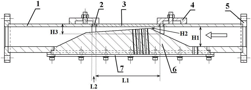
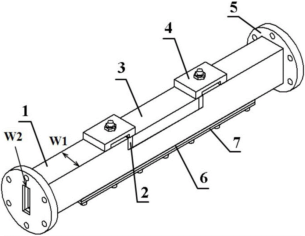
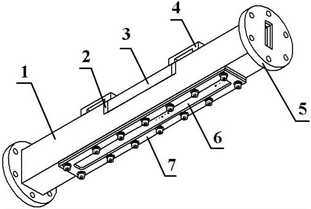
[0046] Such as Figure 1-3 As shown, a detachable cryogenic liquid cavitation flow observation test section consists of a basic flow channel 1, a flow channel lower panel 6, a visual observation window 3, a buffer gasket 2, a compression gasket 7, and a flange plate 5 , temperature sensor and pressure sensor.

[0047] Connection relationship: the temperature sensor and the pressure sensor are installed on the lower panel 6 of the flow channel through the mounting holes; the lower panel 6 of the flow channel is connected to the inner pipe of the basic flow channel 1 through the notch below the basic flow channel 1; and then through the compression gasket 7 is fixedly connected to the basic flow channel 1; the visual observation window 3 is placed at the notch above the basic flow channel 1, and two buffer gaskets 2 are respectively installed on both sides of the visual observation window 3; the connection bayonet 4 is fixedly connected to the basic Above the flow channel 1; fl...


PUM

PropertyMeasurementUnit
Heightaaaaaaaaaa

Abstract

The invention relates to a detachable cryogenic liquid cavitation flow observational test section, which belongs to the technical field of fluid mechanical engineering, cryogenic engineering and aerospace engineering. The detachable cryogenic liquid cavitation flow observational test section comprises temperature sensors and pressure sensors, wherein the temperature sensors and the pressure sensors are installed on a runner lower panel through installation holes; the runner lower panel is in contact connection with a pipeline inside a basic runner through a notch at the lower part of the basic runner, and is fixedly connected on the basic runner through a pressing gasket; a visual observation window is formed in a notch at the upper part of the basic runner, and two buffer gaskets are installed on both sides of the visual observation window separately; a connecting bayonet is fixedly connected on the basic runner; and both sides of the basic runner are provided with flange plates. The detachable cryogenic liquid cavitation flow observational test section is assembled by adopting a plurality of parts, is simple in structure, has few components, greatly reduces cost when compared with an integrated visual test section made of glass materials entirely, is convenient in detachment and installation, and is not prone to damage during the detachment and installation process.

Description

technical field [0001] The invention relates to a cavitation test device, in particular to a detachable low-temperature liquid cavitation test section, which belongs to the technical fields of fluid mechanical engineering, cryogenic engineering and aerospace engineering. Background technique [0002] When the internal partial pressure of the liquid at a certain temperature is reduced to the saturated vapor pressure of the liquid, vaporization will occur, and the gas dissolved in the liquid will also precipitate out to form bubbles (also known as voids, cavities). After the flow moves to a place of higher pressure, the vapor in the bubble recondenses and the bubble collapses. The process of the generation, development, and collapse of cavitation in this liquid flow, as well as the resulting series of physical and chemical changes, are called cavitation. The occurrence of cavitation often leads to a decrease in machine efficiency and causes problems such as vibration, noise, ...

Claims


Application Information

Patent Timeline
IPC IPC(8): G01M10/00G01N11/04
CPCG01M10/00G01N11/04
Inventor 王国玉陈泰然黄彪张敏弟刘影高德明
Owner BEIJING INSTITUTE OF TECHNOLOGYGY
Why Eureka
Try Eureka