
Conductor electrical connection device

An electrical connection and conductor technology, which is applied to the parts, coupling devices, circuits and other directions of the connection device, can solve the problems of high requirements on the conductor assembly process, small error tolerance rate of assembly errors, etc., to improve assembly quality, reduce assembly stress, and reduce The effect of assembly accuracy requirements

Inactive Publication Date: 2016-10-26
平高集团威海高压电器有限公司 +2
View PDF9 Cites 3 Cited by
  • Summary
  • Abstract
  • Description
  • Claims
  • Application Information

AI Technical Summary

Problems solved by technology

[0003] The purpose of the present invention is to provide a conductor electrical connection device to solve the technical problems in the prior art that the device for realizing the two-conductor-corresponding-conduction connection requires high conductor assembly process and low assembly error tolerance rate

Method used


Image

  • Conductor electrical connection device
  • Conductor electrical connection device
  • Conductor electrical connection device

Examples


Embodiment Construction

[0032] Embodiments of the present invention will be further described below in conjunction with the accompanying drawings.

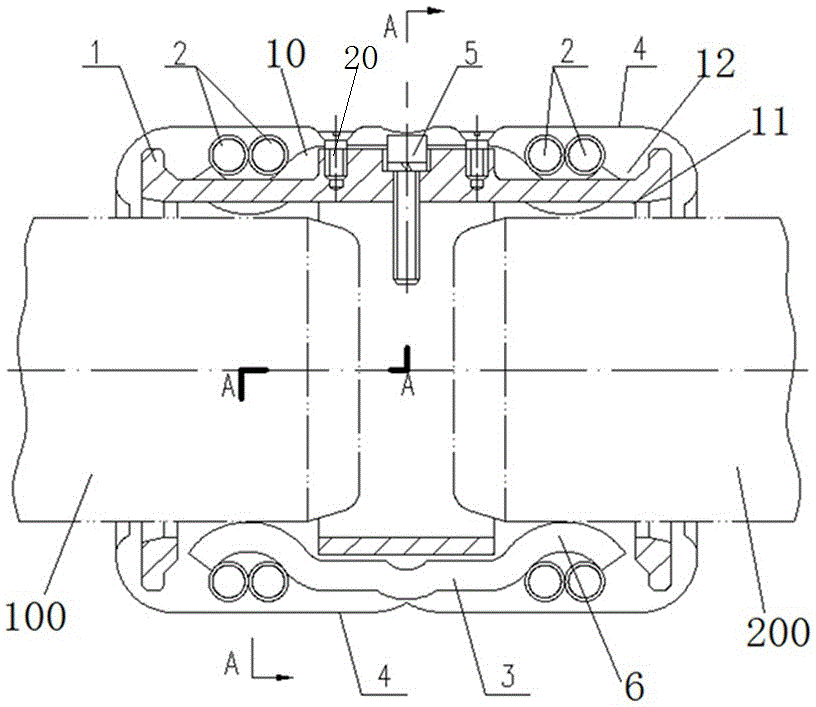
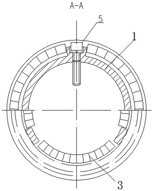
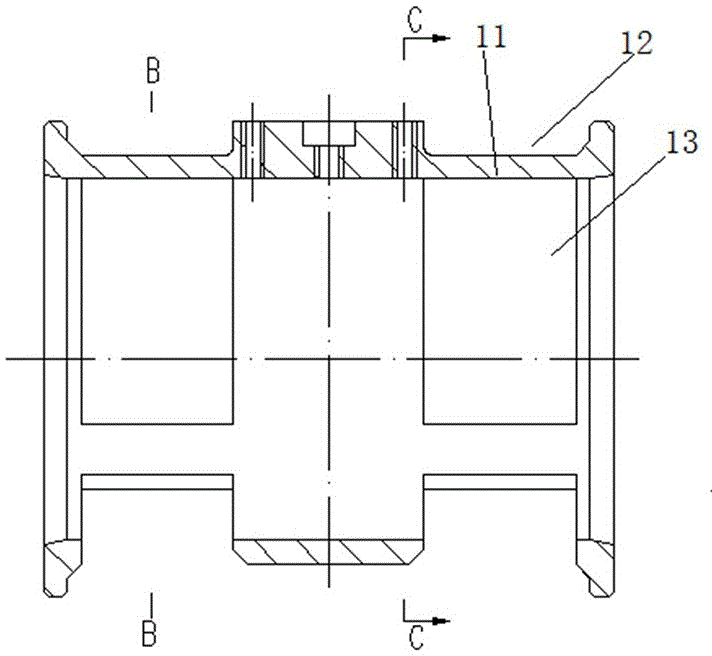
[0033] Specific embodiments of the conductor electrical connection device provided by the present invention, such as Figure 1 to Figure 9 As shown, the electrical connection device in this embodiment includes contact finger installation sleeves 1 extending in the left and right directions, and the left and right sides of the contact finger installation sleeve 1 respectively have a plug hole section 11 for connecting with two plug holes to be electrically connected. The corresponding ends of the conductors are fitted with gap plugs.

[0034] The contact finger mounting sleeve 1 is provided with conductive contact finger structures 10, and three conductive contact finger structures 10 are evenly distributed along the circumferential direction, and each conductive contact finger structure 10 has two elastic contact finger parts arranged at intervals along ...


PUM


Abstract

The invention relates to a conductor electrical connection device comprising a contact finger installing sleeve which extends along a left-and-right direction. The contact finger installing sleeve is provided with a plugging hole segment which sleeves the corresponding end part of a plugging conductor under conductive connection in a clearance way. The contact finger installing sleeve is provided with a conductive contact finger structure. The conductive contact finger structure is provided with an elastic contact finger part which stretches to the plugging hole segment in a suspension way and is arranged in a way of inwardly protruding out of the internal hole wall of the plugging hole segment so as to be conductively contacted with the corresponding plugging conductor. The elastic contact finger part can deform in the radial direction of the contact finger installing sleeve under the abutting effect of the plugging conductor so that the radial position of the plugging conductor in the contact finger installing sleeve can be adjusted, effective conductive contact of the electrical connection device and the plugging conductor can be realized through radial deformation of the elastic contact finger part even deviation exists between the original installing position of the plugging conductor and the design position, and thus the assembling accuracy requirement for the plugging conductor can be reduced and the assembling efficiency can be enhanced.

Description

technical field [0001] The invention relates to a conductor electrical connection device. Background technique [0002] In GIS equipment, the conductors between the components need to be electrically connected to each other. Generally, there are two connection methods: one is that the two planes of the two conductors are in direct contact, and the connection is fastened by bolts; the second is that the fixed electrical connection is used. For example, in the Chinese utility model patent whose authorized announcement number is CN201937177U, the electrical connection device for realizing the conductive connection between the conductive contact and the conductive rod is provided. A number of plum contact fingers are evenly distributed in the cover. The contact is electrically connected to the conductive rod through the plum contact finger structure. A guide bolt for plugging is provided in the center of the conductor block. Using the guide bolt and the guide structure on the co...

Claims


Application Information

Patent Timeline
Patent Type & Authority Applications(China)
IPC IPC(8): H01R13/11H01R4/60
CPCH01R4/60H01R13/111
Inventor 周茂欣刘威景清源黄腾
Owner 平高集团威海高压电器有限公司
Learn More