Signal source, error code tester, signal generation method and error code test method

A signal source and tester technology, applied in the direction of using signal quality detectors for error detection/prevention, correct operation testing, digital transmission systems, etc., can solve problems such as expensive prices, increased research and development or manufacturing cost pressures, and achieve cost Low cost, reduced product testing and manufacturing costs, easy to achieve effects

Active Publication Date: 2016-10-26
SOURCE PHOTONICS CHENGDU
View PDF11 Cites 2 Cited by
  • Summary
  • Abstract
  • Description
  • Claims
  • Application Information

AI Technical Summary

Problems solved by technology

However, the current situation is that the production of signal generation and bit error detectors has been monopolized by several manufacturers (such as Agilent (Keysight), Tektronix (TEKTRONIX) and Anritsu), resulting in very expensive prices (about 150,000 US dollars to 300,000 US dollars) , which makes the manufacturers or research and development institutions of transmission products mass-produce and promote commercial applications of products, increasing the pressure of great research and development or manufacturing costs

Method used


Image

  • Signal source, error code tester, signal generation method and error code test method
  • Signal source, error code tester, signal generation method and error code test method

Examples


Embodiment Construction

[0030] The following will clearly and completely describe the technical solutions in the embodiments of the present invention with reference to the accompanying drawings in the embodiments of the present invention. Obviously, the described embodiments are only some, not all, embodiments of the present invention. The components of the embodiments of the invention generally described and illustrated in the figures herein may be arranged and designed in a variety of different configurations. Accordingly, the following detailed description of the embodiments of the invention provided in the accompanying drawings is not intended to limit the scope of the claimed invention, but merely represents selected embodiments of the invention. Based on the embodiments of the present invention, all other embodiments obtained by those skilled in the art without making creative efforts belong to the protection scope of the present invention.

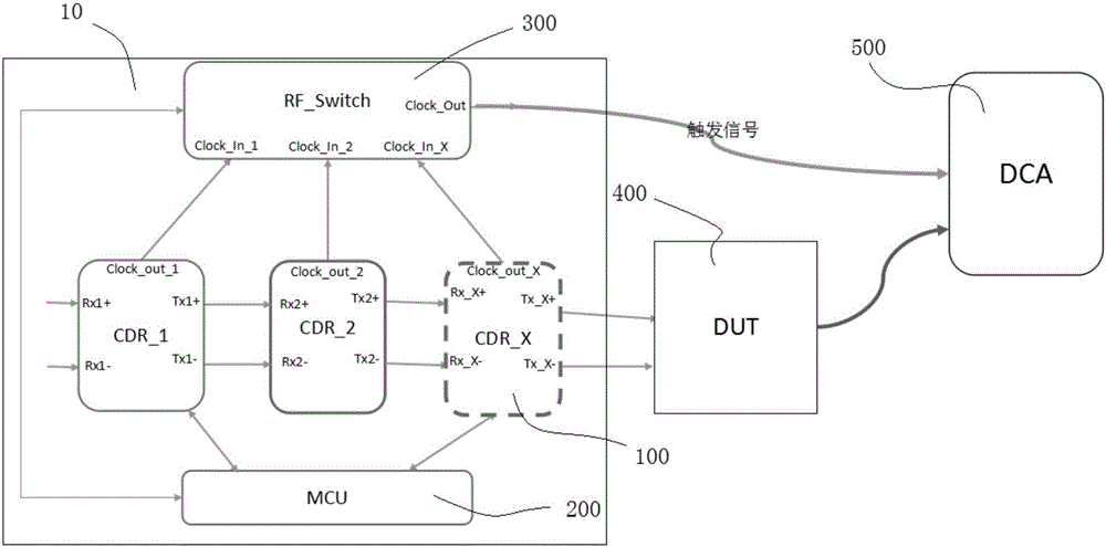
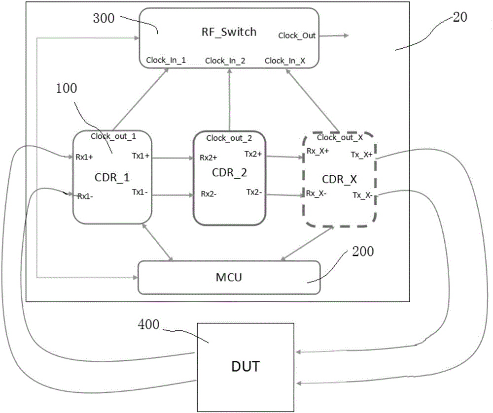
[0031] In order to ensure the quality of ex-factory ...


PUM


Abstract

The invention relates to a signal source, an error code tester, a signal generation method and an error code test method. The signal source comprises a micro controller and at least two clock data recovery chips, wherein the at least two clock data recovery chips are cascaded, and the transmission rates of test signals generated by each clock data recovery chip are different; and the micro controller is used for setting that one clock data recovery chip in the at least two clock data recovery chips generate the test signals, and the other clock data recovery chips are in a bypass mode. According to the signal source, the error code tester, the signal generation method and the error code test method provided by the embodiment of the invention, the at least two clock data recovery chips are adopted, the at least two clock data recovery chips are cascaded, and the micro controller controls one clock data recovery chip to generate the test signals with the necessary rate, so that the cost is low, the instrument structure or method steps are simple, and multi-rate or full-rate error code detection can be achieved.

Description

technical field [0001] The invention relates to the technical field of transmission equipment, in particular to a signal source, a code error tester, a signal generation method and a code error test method. Background technique [0002] In the current transmission products, the generation of high and low frequency signals and bit error transmission testing have always been an important part of the transmission product industry (especially the optical module industry). With the increasing demand for single-wavelength 25G and 100G (25Gx4) R&D and production of leading transmission products has become a field of competition for various manufacturers or related research units, which makes the signal generation and bit error testing equipment for necessary testing of R&D and production transmission products abnormal. importance. However, the current situation is that the production of signal generation and bit error detectors has been monopolized by several manufacturers (such a...

Claims


Application Information

Patent Timeline
Patent Type & Authority Applications(China)
IPC IPC(8): H04L1/20H04L1/24
CPCH04L1/203H04L1/244Y02D10/00
Inventor 田永猛彭奇汪国强
Owner SOURCE PHOTONICS CHENGDU
Why Eureka
Try Eureka