
Sputtering target, optical functional film and laminated wiring film

A technology of optical function and sputtering target, which is applied in optics, optical components, sputtering coating, etc., can solve problems such as difficult to use touch panels, and achieve the effects of reduced masking, excellent reliability, and satisfactory reliability

Active Publication Date: 2019-10-18
MITSUBISHI MATERIALS CORP
View PDF17 Cites 0 Cited by
  • Summary
  • Abstract
  • Description
  • Claims
  • Application Information

AI Technical Summary

Problems solved by technology

However, there is a problem that since the metal wiring using this metal thin film shows good reflection characteristics to reflect external light, the metallic luster of the wiring pattern can be seen from the outside of the panel, making it difficult to use the touch panel.

Method used


Image

  • Sputtering target, optical functional film and laminated wiring film
  • Sputtering target, optical functional film and laminated wiring film
  • Sputtering target, optical functional film and laminated wiring film

Examples


Embodiment

[0037] Next, the sputtering target of the present invention and an optical functional film formed using the sputtering target will be specifically described below using examples.

[0038] [Example]

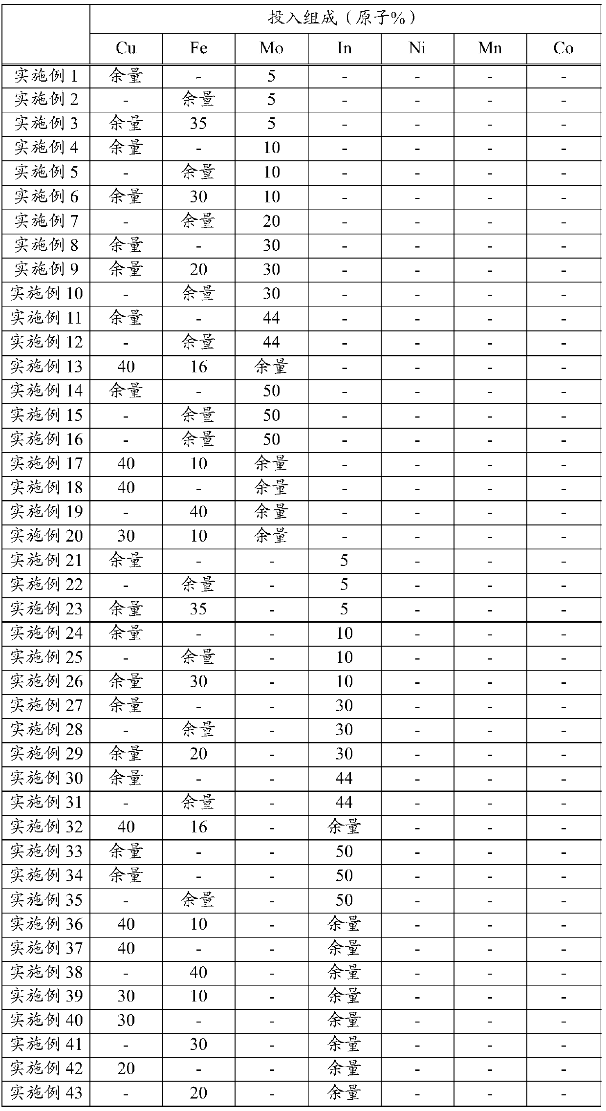
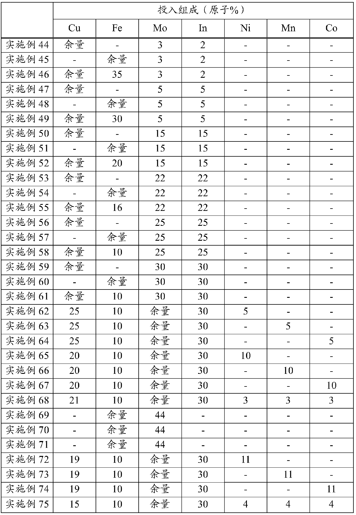
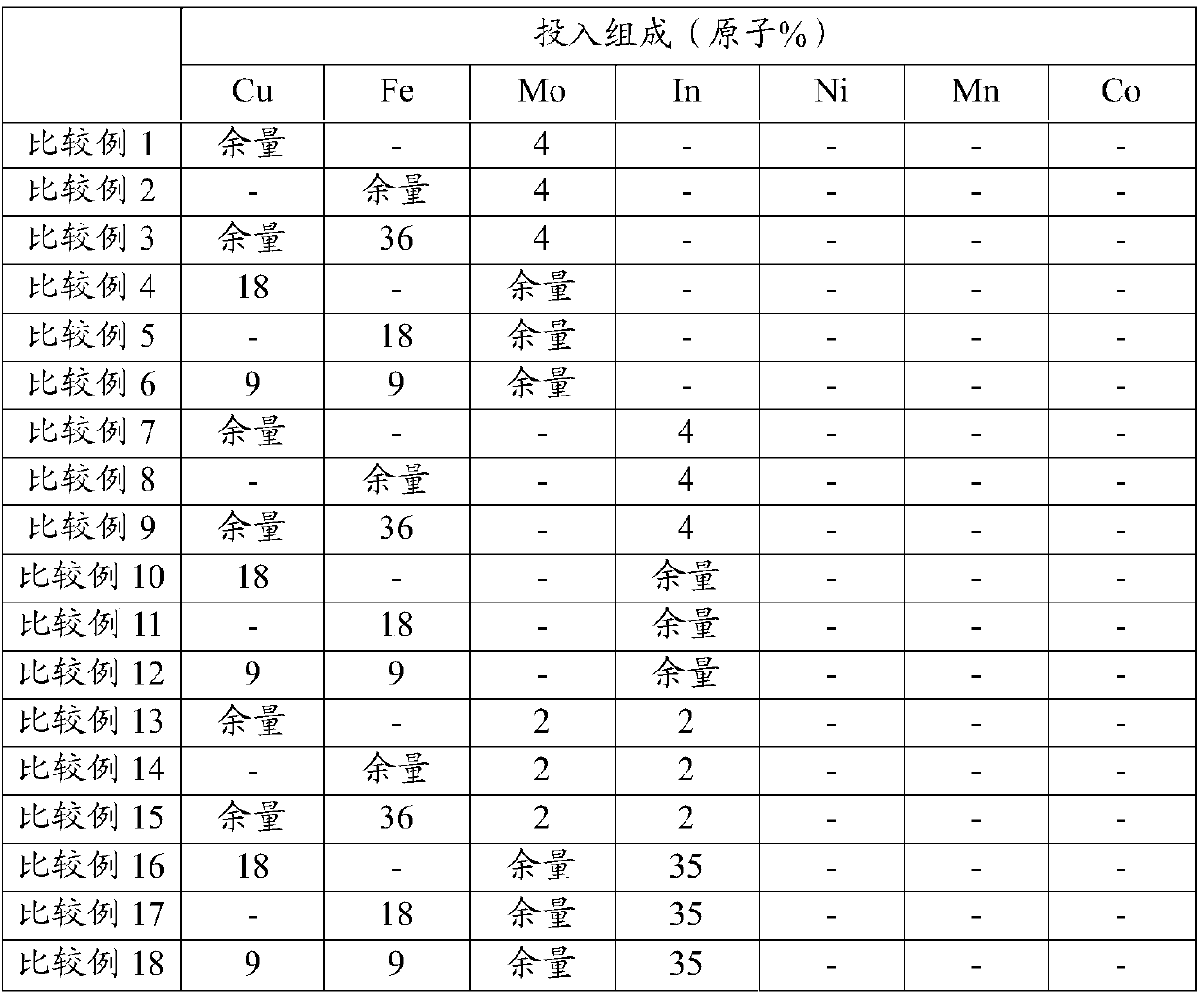
[0039] First, to fabricate the sputtering target, MoO 2 Powder, In 2 o 3 powder, CuO powder, Fe 3 o 4 powder, NiO powder, Mn 2 o 3 Powder and Co 3 o 4 powder. Next, they were weighed so that the target material composition ratios (metal only) shown in Table 1 and Table 2 were obtained, and each powder weighed was filled in a mixing device and mixed to prepare Examples 1-6, 9- Mixed powders of 13, 15, 17-18, 20-26, 28-32, 35-39, 41, 43-75. Using the mixed powder of each example as a raw material, temperature: 700°C, pressure: 300kgf / cm 2 (29.4 MPa) was hot-pressed in vacuum for 3 hours to produce a sintered body. These sintered bodies were machined to a diameter of 152.4 mm and a thickness of 6 mm, and were pasted on a Cu backing plate with In solder to produce examples...


PUM

PropertyMeasurementUnit
particle diameteraaaaaaaaaa
thicknessaaaaaaaaaa
surface roughnessaaaaaaaaaa

Abstract

This sputtering target: includes the metallic elements Mo and / or In and Cu and / or Fe as main components; contains 5-80at% of Mo and / or In and 20-95at% of Cu and / or Fe, and comprises some or all of the metal elements in the form of oxides.

Description

technical field [0001] The present invention relates to a sputtering target, an optical functional film, and a laminated wiring film for sputtering forming an optical functional film laminated on a metal thin film and reducing metal reflection. [0002] This application claims priority based on Patent Application No. 2014-132524 filed in Japan on June 27, 2014 and Patent Application No. 2015-116826 filed in Japan on June 9, 2015, and uses the contents thereof here. Background technique [0003] In recent years, projected capacitive touch panels have been used as input means for portable terminal devices and the like. In this touch panel, when a finger approaches a sensing electrode disposed on a substrate of the touch panel, capacitance is formed between the fingertip and the electrode. In the touch panel of this form, a touch position is detected by a control circuit or the like based on the change in capacitance. In order to detect the touch position, sensing electrodes ...

Claims


Application Information

Patent Timeline
Patent Type & Authority Patents(China)
IPC IPC(8): C23C14/34C04B35/00C22C9/00C22C9/05C22C9/06C22C27/04C22C28/00C22C38/00C22C38/12C23C14/08G02B1/113
CPCC04B35/00C22C9/00C22C9/05C22C9/06C22C27/04C22C28/00C22C38/00C22C38/12C23C14/08C23C14/34G02B1/113
Inventor 斋藤淳张守斌盐野一郎
Owner MITSUBISHI MATERIALS CORP
Learn More