Cyclic ink supply system
A technology of supplying system and ink, applied in printing and other directions, can solve problems affecting the quality and effect of printed products, ink waste, etc., and achieve the effect of avoiding ink precipitation, avoiding color difference, and reducing color difference
- Summary
- Abstract
- Description
- Claims
- Application Information
AI Technical Summary
Problems solved by technology
Method used
Image
Examples
Embodiment 1
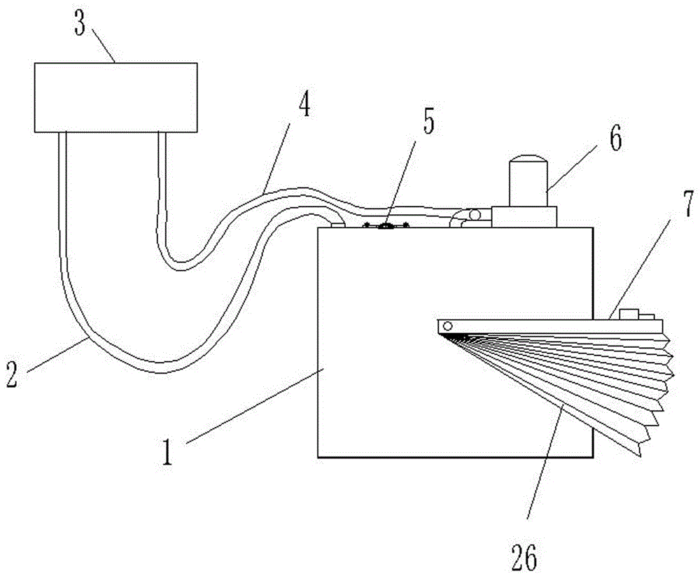
[0042] Embodiment one, such as Figure 6 shown. The automatic induction fire extinguishing device 7 includes a foldable fire extinguishing blanket 26, a support frame 22, an electric control lock 24, a temperature sensor 25 and a controller. The two ends of the support frame 22 are connected to the two sides of the ink supply cartridge 1 through torsion spring rotation; the electric control lock 24 is fixed on the bracket 23 outside the ink supply cartridge 1, and the dead bolt of the electric control lock 24 stretches out and presses on the support frame 22 Keep the support frame 22 in a horizontal position or tilt downward, and the support 23 is fixedly connected with the ink supply cartridge 1; the temperature sensor 25 is fixed on the box body of the ink supply cartridge 1, and the temperature sensor 25 and the electric control lock 24 are all connected with the controller. When the temperature sensor 25 senses that the temperature exceeds the set value, the electric cont...
Embodiment 2
[0043] Example two such as Figure 7 shown. The support frame 22 includes a fixed frame 29 and a movable frame 28, the fixed frame 29 is horizontally fixed on the outside of the ink supply cartridge 1, the two ends of the movable frame 28 are rotatably connected to the both sides of the ink supply cartridge 1 by a torsion spring, and the movable frame 28 is positioned at the fixed Above the frame 29, the foldable fire blanket 26 is connected between the fixed frame 29 and the movable frame 28. The movable frame 28 is in a horizontal state under the action of the electric control lock 24 and overlaps with the fixed frame 29 below. When the temperature sensor 25 senses When the temperature exceeds the set value, the electric control lock 24 is powered off, the dead bolt of the electric control lock 24 is retracted, and the movable frame 28 is turned up to the other side of the ink supply cartridge 1, and the foldable fire blanket 26 is driven to cover the entire ink supply cartr...
Embodiment 3
[0044] Embodiment three such as Figure 8 , Figure 9 shown. The electric control lock 24 is fixed on the support frame 22, and the bracket 23 is provided with a hook 27. When the ink supply system works normally, the dead bolt of the electric control lock 24 stretches out, and the hook 27 hooks upward on the dead bolt of the electric control lock 24. , when the temperature sensor 25 senses that the temperature exceeds the set value, the electric control lock 24 will be powered off, the dead bolt of the electric control lock 24 will be withdrawn, the hook 27 will break away from the control of the electric control lock 24, and the support frame 22 will turn up to the position of the ink supply cartridge 1. On the other side, the folded fire blanket 26 is driven to cover the entire ink supply cartridge 1, so that the ink supply cartridge 1 is isolated from the outside air.
[0045] Figure 10 It is the control schematic diagram of the automatic induction fire extinguishing d...
PUM
 Abstract
Description
Claims
Application Information
 - R&D
- Intellectual Property
- Life Sciences
- Materials
- Tech Scout
- Unparalleled Data Quality
- Higher Quality Content
- 60% Fewer Hallucinations
Browse by: Latest US Patents, China's latest patents, Technical Efficacy Thesaurus, Application Domain, Technology Topic, Popular Technical Reports.
© 2025 PatSnap. All rights reserved.Legal|Privacy policy|Modern Slavery Act Transparency Statement|Sitemap|About US| Contact US: help@patsnap.com


