
Blade casting die, application of blade casting die and blade forming method

A technology for casting molds and blades, applied in casting molding equipment, molds, mold components, etc., can solve the problems of coarse grains on the surface of cooling speed, poor surface finish, insufficient pouring, etc., and achieve less surface defects and better blade quality. , block reasonable effect

Active Publication Date: 2016-11-09
HIMILE MECHANICAL SCI & TECH (SHANDONG) CO LTD
View PDF8 Cites 2 Cited by
  • Summary
  • Abstract
  • Description
  • Claims
  • Application Information

AI Technical Summary

Problems solved by technology

If the casting temperature of the alloy liquid is too low, the mold temperature may be too low, insufficient pouring, cold shut; if the casting temperature is too high, the mold temperature is too high, and the cooling rate is too small, the surface grains may be coarse and the surface finish may be poor

Method used


Image

  • Blade casting die, application of blade casting die and blade forming method
  • Blade casting die, application of blade casting die and blade forming method
  • Blade casting die, application of blade casting die and blade forming method

Examples


Embodiment 1

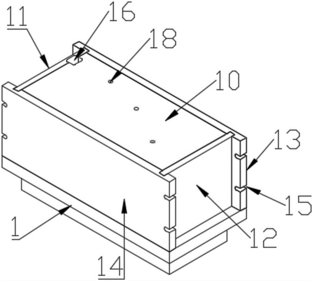
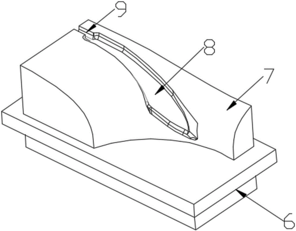
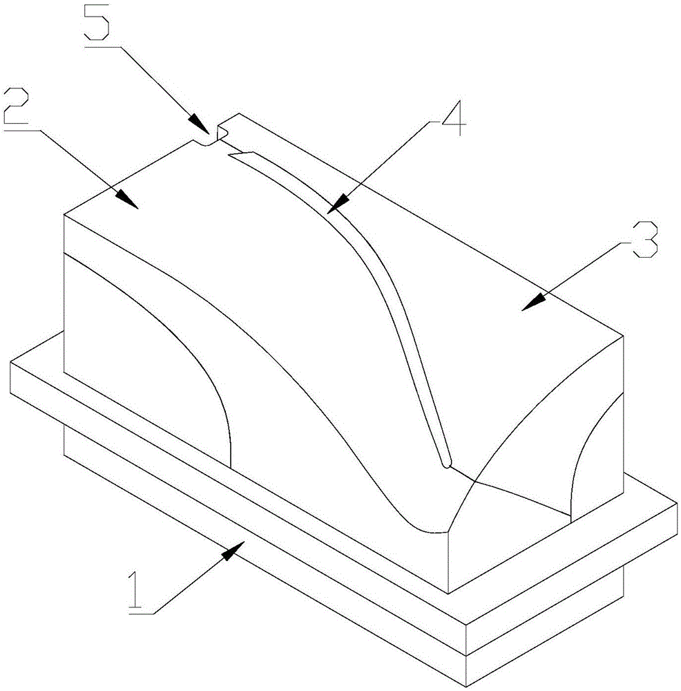
[0047] like Figure 1-Figure 3As shown, a casting mold for a blade includes an upper mold and a lower mold 1 which are arranged correspondingly up and down, and a first groove 8 for forming a three-dimensional distortion of the lower edge of the blade is provided at the joint between the lower mold 1 and the upper mold; the upper mold It includes the first upper mold assembly 2 and the second upper mold assembly 3 which are arranged in front and back correspondingly, the two ends of the butt joint surfaces of the first upper mold assembly 2 and the second upper mold assembly 3 are bonded, and the first upper mold assembly The middle part of part 2 and the second upper mold assembly 3 has a hollow space 4 for forming the main part of the blade, which is used for molding the thin-walled part of the main body of the blade, wherein the surface of the hollow space is twisted and extended along the surface of the blade in three dimensions; the upper part of the upper mold is connecte...

Embodiment 2

[0064] like Figure 5 and Figure 7 As shown, one end of the first upper die assembly 2 and the second upper die assembly 3 does not fit, and a triangular mold 19 is set at the corner of the first upper die assembly 2 and the second upper die assembly 3 , the triangular mold 19 includes the first triangular mold assembly 20 and the second triangular mold assembly 21 correspondingly arranged before and after, and the first triangular mold assembly 20 and the second triangular mold assembly 21 fit together; the triangular mold is positioned at the gate and constitutes a part of the runner, which is convenient for removing the gate and demoulding after the low-melting alloy is solidified.

[0065] The outer boundary of the triangular mold 19 is provided with a runner 5 connected to the first groove 8 of the lower mold 1 near the third limiting plate 13; pouring is carried out at the runner 5, and the casting melt flows out of the mold along the runner. The first groove on the l...

Embodiment 3

[0067] A method for forming a blade, comprising the following steps:

[0068] Step 1: cleaning the surfaces of the component parts of the blade casting mold, assembling the blade casting mold for use, and coating the inner surface of the blade casting mold with a release agent;

[0069] Step 2: Weigh the casting raw materials according to the set requirements, and clean the dust on the surface of the casting raw materials;

[0070] Step 3: Put the blade casting mold in the dryer to preheat, and use the temperature measurement module to monitor the temperature of the blade casting mold until the required temperature is set to stop preheating;

[0071] Step 4: Heat the casting raw material to melt it to form a casting raw material solution, use the temperature measurement module to monitor the temperature of the casting raw material solution until the required temperature is set and stop heating;

[0072] Step 5: removing impurities on the surface of the casting raw material so...


PUM


Abstract

The invention discloses a blade casting die, application of the blade casting die and a blade forming method. The blade casting die comprises an upper die body and a lower die body which are correspondingly arranged. A first groove used for forming the lower edge portion of a blade is formed in the position, matched with the upper die body, of the lower die body. The upper die body comprises a first upper die assembly and a second upper die assembly which are arranged in a front-back corresponding manner. A gap used for forming a body part of the blade is formed between the first upper die assembly and the second upper die assembly. The upper portion of the upper die body is matched with a cover plate, and a second groove used for forming the upper edge portion of the blade is formed at the position, matched with the upper die body, of the cover plate. By means of the blade casting die, the application of the blade casting die and the blade forming method, due to the fact that the upper die body, the lower die body and the cover plate are matched in a blocking manner, the three-dimensional twisted blade can be manufactured. Due to the forming method, the surface of the die can be kept at a certain temperature, high-temperature molten liquid can be rapidly cooled at the same time after the space of the die is filled with the liquid, the blade forming quality is good, and surface defects are few.

Description

technical field [0001] The invention belongs to the field of casting, and relates to a blade casting mold used for products with blades, in particular to a blade casting mold, its application and a blade forming method. Background technique [0002] In the manufacturing process of products with blades, especially in the manufacturing process of closed impellers. The blade parts are often three-dimensionally twisted and manufactured by direct machining, which is very difficult or even impossible to process. [0003] In the existing blade manufacturing method, the mold is set to be molded in the shape of the blade. However, when casting blades with complex shapes, especially three-dimensionally twisted blades, it is difficult to directly set the mold into the shape of the blade. Because this is the difficulty of transforming the difficulty of blade casting into the difficulty of mold processing. Compared with blade casting, the machining process of the mold is more complica...

Claims


Application Information

Patent Timeline
Patent Type & Authority Applications(China)
IPC IPC(8): B22C9/22B22C9/08
CPCB22C9/082B22C9/22
Inventor 张伟韩桂强张增超别玉月孙燕杰
Owner HIMILE MECHANICAL SCI & TECH (SHANDONG) CO LTD
Learn More