Selective laser melting forming equipment and forming method thereof

A technology for laser selective melting and forming equipment, which is applied in processing and manufacturing, additive manufacturing, solid material additive processing, etc., and can solve problems that restrict the promotion and application of laser selective melting and forming technology, reduce the efficiency of forming equipment, and increase product manufacturing costs. , to save the forming time, reduce the processing cost and improve the efficiency.

Inactive Publication Date: 2016-11-09
XIAN BRIGHT ADDTIVE TECH CO LTD
View PDF10 Cites 37 Cited by
  • Summary
  • Abstract
  • Description
  • Claims
  • Application Information

AI Technical Summary

Problems solved by technology

With this powder spreading method, the return process of the powder spreading device greatly wastes the forming time, reduces the efficiency of the forming equipment, and increases the manufacturing cost of the product
In addition, most of the laser selective melting forming equipment currently on the market is single-cylinder forming, that is, only a single part can be formed at a time, which restricts the promotion and application of laser selective melting forming technology

Method used


Image

  • Selective laser melting forming equipment and forming method thereof
  • Selective laser melting forming equipment and forming method thereof
  • Selective laser melting forming equipment and forming method thereof

Examples


Embodiment Construction

[0026] The present invention will be described in detail below in conjunction with the accompanying drawings and specific embodiments.

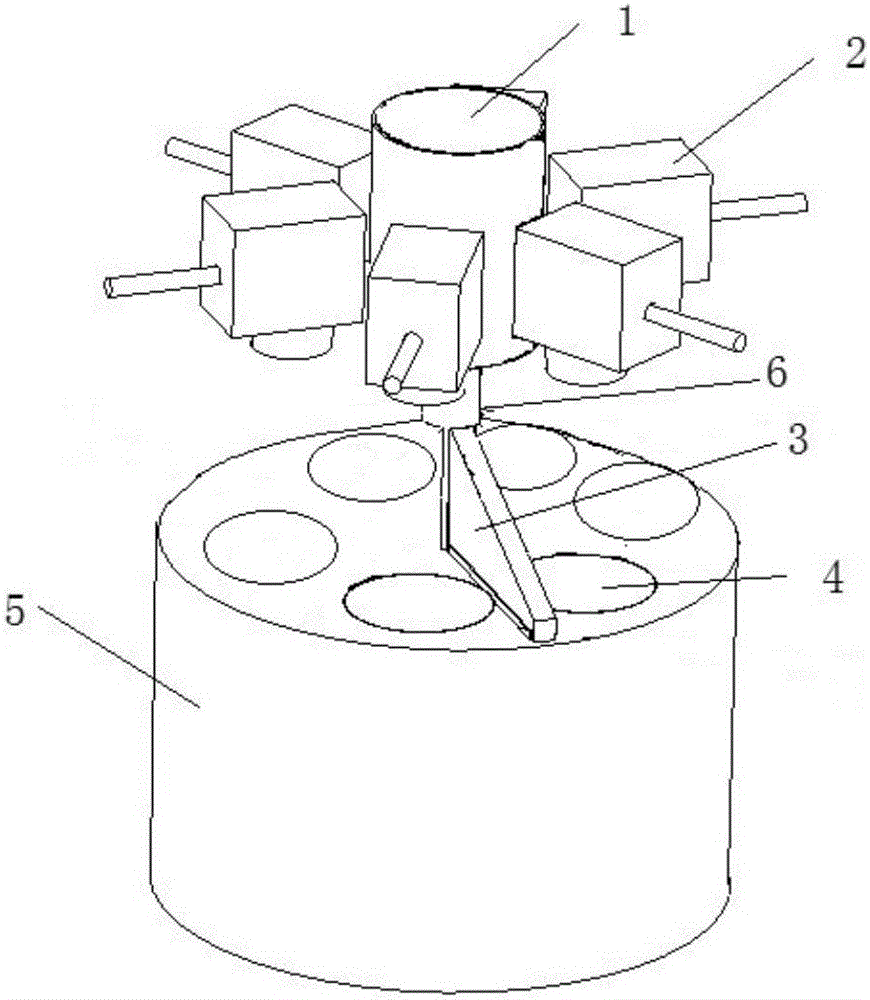
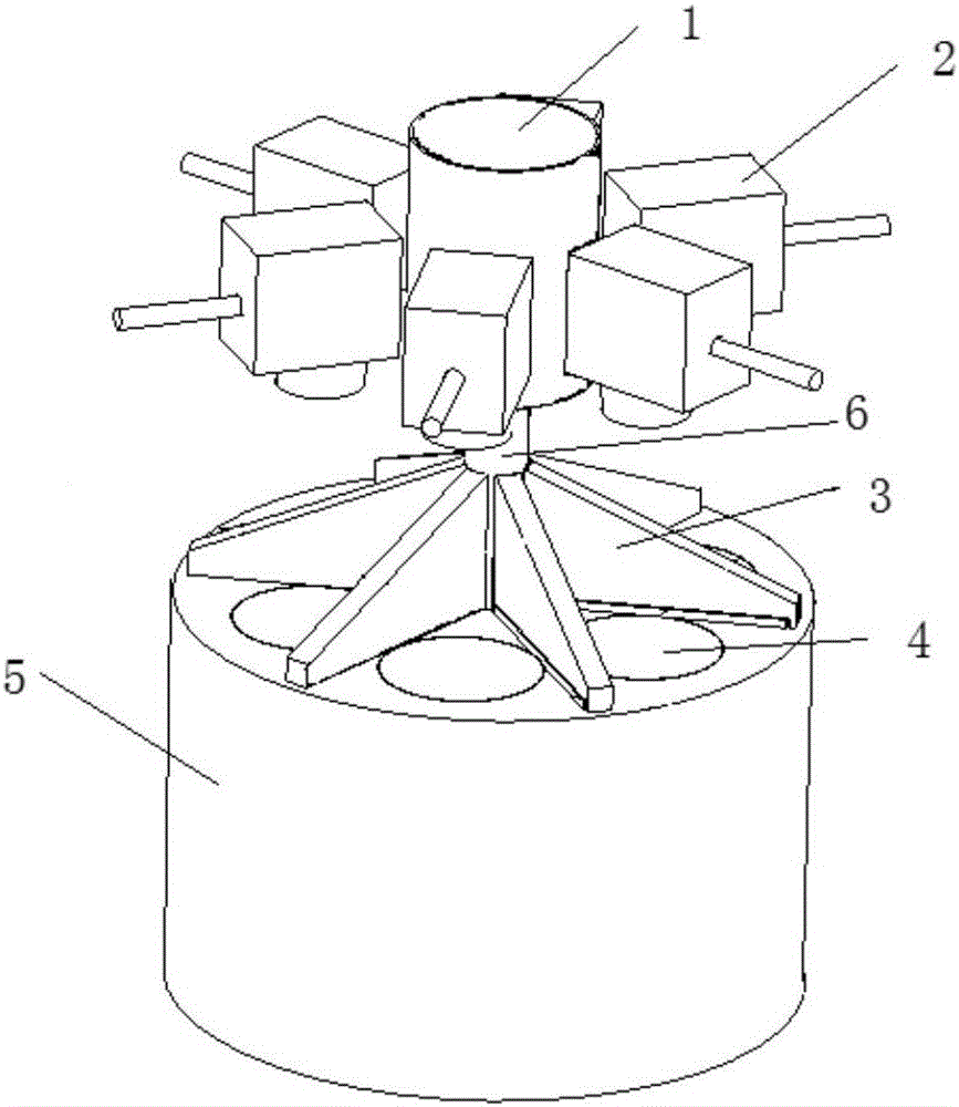
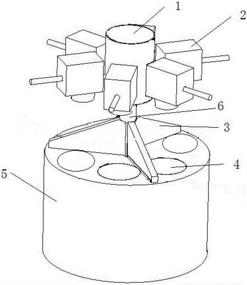
[0027] The invention provides a laser selective melting and forming equipment, which includes a general equipment platform 5, a liftable forming platform 4, a rotatable powder feeding device and a laser system 2, and the rotation center of the rotatable powder feeding device is located on the equipment general platform 5 At the center of the equipment platform 5, there are at least two through holes. The through holes extend downward along the upper surface of the equipment platform. The forming platform 4 is embedded in the through holes and can move up and down in the through holes. The through holes and The forming platform 4 constitutes the forming cylinder of the laser selective melting forming equipment, and the laser system 2 is located above the liftable forming platform for scanning and melting the powder layer on the surface of the c...


PUM


Abstract

The invention discloses selective laser melting forming equipment which comprises a chief equipment platform, lifting forming platforms, a rotatable powder supplying and paving device and laser systems. The chief equipment platform is provided with through holes which downwards extend along the upper surface of the chief equipment platform, the forming platforms are embedded in the through holes and can move up and down in the through holes, and the laser systems are located above the lifting forming platforms. The invention further discloses a forming method which specifically includes the following steps that 1, base materials are placed on the forming platforms, and the upper surfaces of the base materials are made to be aligned with the upper surface of the chief equipment platform; 2, powder is added into a powder supplying bin, a hollow rotating shaft rotates to pave the surface of each base material with a layer of powder; 3, the laser systems are started to scan the powder layers in the areas of the forming platforms; and 4, after scanning is completed, the forming platforms fall by the distance of the thickness of one layer of powder, and the second step of powder paving and the third step of scanning are repeated till forming is completed. The selective laser melting forming equipment and the forming method thereof are high in forming efficiency.

Description

technical field [0001] The invention belongs to the technical field of laser additive manufacturing, and relates to a laser selective melting forming equipment and a forming method using the laser selective melting forming equipment. Background technique [0002] Laser selective melting forming technology is an advanced laser additive manufacturing technology developed on the basis of prototype manufacturing technology. It uses special software to slice and layer the three-dimensional digital model of the part. After obtaining the profile data of each section, it uses high-energy laser The beam selectively melts metal powder layer by layer according to the profile data, which is a method of manufacturing three-dimensional solid parts by layer-by-layer powder spreading, layer-by-layer melting, solidification and accumulation. The laser selective melting forming technology breaks through the traditional ideas of deformation forming and removal forming in the traditional manufa...

Claims


Application Information

Patent Timeline
Patent Type & Authority Applications(China)
IPC IPC(8): B22F3/105B33Y10/00B33Y30/00
CPCB33Y10/00B33Y30/00B22F10/00B22F12/226B22F12/52B22F10/28B22F12/67B29C64/153Y02P10/25
Inventor 刘泽众杨东辉薛蕾
Owner XIAN BRIGHT ADDTIVE TECH CO LTD
Why Eureka
Try Eureka