
Laser marking machine

A laser marking machine and laser marking technology, applied in the field of laser marking machines, can solve problems such as affecting production efficiency, reducing work efficiency, reducing equipment utilization, etc., to improve marking efficiency and marking accuracy, and reduce work. cost, improve work efficiency

Inactive Publication Date: 2016-11-09
平湖拓伟思自动化设备有限公司
View PDF15 Cites 4 Cited by
  • Summary
  • Abstract
  • Description
  • Claims
  • Application Information

AI Technical Summary

Problems solved by technology

[0003] The traditional parts pass through the laser marking machine, only by placing the parts in the position corresponding to the laser marking machine, and the laser marking machine uses a high-energy-density laser to irradiate a certain part of the workpiece to vaporize the surface material Or a chemical reaction of color change, leaving a permanent mark; but for parts that require multiple angles and different orientations for marking, it is necessary to cooperate with a professional workbench, set up a working interface, and perform subsequent marking after changing the angle and orientation. The standard reduces work efficiency, and requires a lot of manual cooperation, which increases work costs; while wasting time, it also reduces the utilization rate of equipment and affects production efficiency

Method used


Image

  • Laser marking machine
  • Laser marking machine

Examples


Embodiment

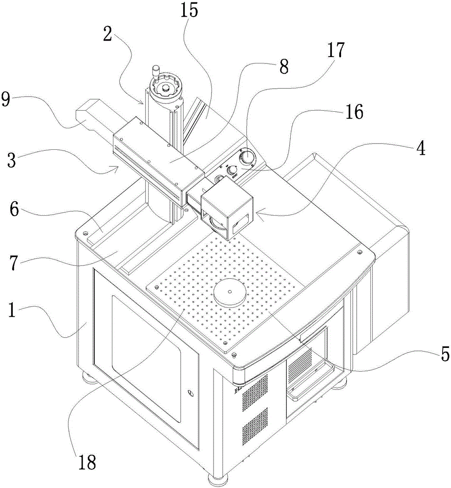
[0021] Example: such as Figure 1-2 As shown, a laser marking machine includes a workbench 1, a lifting device 2 arranged on the workbench 1 and a laser marking device 3, the laser marking device 3 is arranged on the lifting device 2, and the laser marking A laser marking device 4 pointing downward is provided at the end of the marking device 3 , and a marking console 5 is provided on the workbench 1 , and the position of the laser marking device 4 corresponds to the marking console 5 .

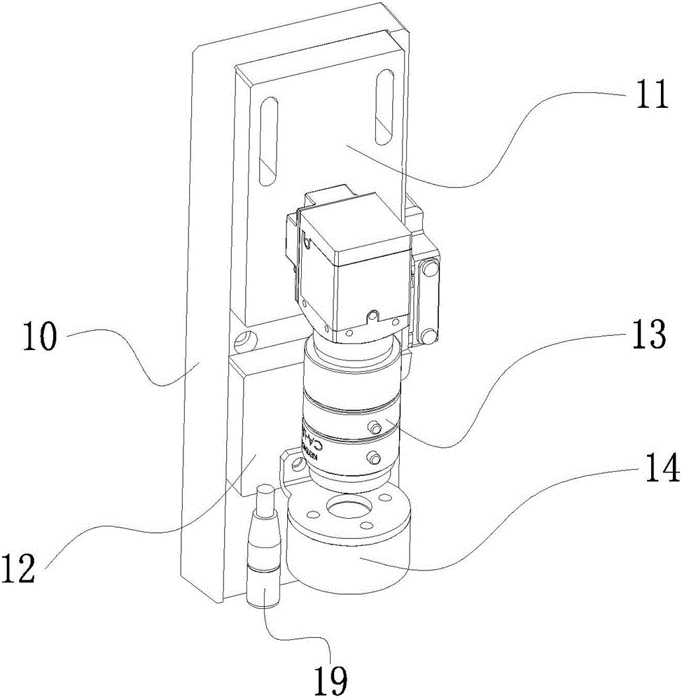
[0022] The rear end of the workbench 1 is fixed with a mounting plate 6, the mounting plate 6 is provided with a slideway 7, and the lifting device 2 is slidably arranged on the slideway 7, and the lifting device 2 moves left and right through the slideway 7; And laser marking device 3 can adjust the height of marking head 19 and CCD camera (laser optical path).

[0023] The workbench 1 is provided with a control device, the control device automatically controls the operating system, and the...


PUM


Abstract

The invention relates to a laser marking machine. The laser marking machine comprises a workbench, a lifting device and a first laser marking device, wherein the lifting device and the first laser marking device are arranged on the workbench. The first laser marking device is arranged on the lifting device. A second laser marking device pointing at the lower portion is arranged at the end portion of the end portion of the first laser marking device, and the workbench is provided with a marking operation table. The second laser marking device corresponds to the marking operation table in position. Compared with the prior art, through mutual cooperation of the lifting device, the first laser marking device and the second laser marking device, the position of the second laser marking device can be adjusted at will through horizontal transverse moving of the lifting device and horizontal longitudinal moving of the first laser marking device, and therefore marking of workpieces at different positions is achieved, the work efficiency is improved, and the work cost is reduced. Meanwhile, a CCD camera corresponds to the marking operation table, the accurate marking position is achieved, and the marking efficiency and the marking precision are improved.

Description

technical field [0001] The invention belongs to the technical field of workpiece marking equipment, and in particular relates to a laser marking machine. Background technique [0002] At present, as the labor cost of the manufacturing industry is getting higher and higher, it is urgent for all walks of life to improve their automation level. In recent years, the Internet intelligent management of workpieces has appeared on the market. With the improvement of the reliability and practicability of lasers, the rapid development of computer technology and the improvement of optical devices, laser marking technology has made great progress; The marking machine has many advantages such as high marking accuracy, fast processing speed, low cost, high automation level, no mechanical extrusion or mechanical stress damage to the processed items, etc., making the application of laser marking machines more and more extensive and popular . [0003] The traditional parts pass through the...

Claims


Application Information

Patent Timeline
Patent Type & Authority Applications(China)
IPC IPC(8): B23K26/362B23K26/70
CPCB23K26/361B23K26/70
Inventor 胡俊顾晓健王如冈
Owner 平湖拓伟思自动化设备有限公司
Learn More