3D printer
A 3D printer and print head technology, applied in the direction of additive processing, etc., can solve the problems of high cost and large size, and achieve the effects of reducing the size of the motor, saving space, and reducing costs
- Summary
- Abstract
- Description
- Claims
- Application Information
AI Technical Summary
Problems solved by technology
Method used
Image
Examples
Embodiment 1
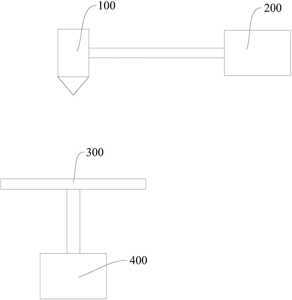
[0034] figure 1 It is the 3D printer in Embodiment 1. In the figure, the meanings of each reference numeral are as follows: 100, extrusion printing head; 200, first motor; 300, lifting platform; 400, second motor.
[0035] Specifically, the 3D printer according to the embodiment of the present invention includes: an extrusion printing head 100 and a first motor 200 for driving the extrusion printing head 100; The second motor 400 of the lifting platform 300; the first motor 200 and the second motor 400 are both BYJ motors. Advantageously, the BYJ motor is specifically selected as 28BYJ48 motor, 35BYJ412 motor, 20BYJ46 motor or 24BYJ48 motor.
[0036]The control system of BYJ motor reads the G-code code inside the SD card and converts it into the electric pulse signal corresponding to the stepping motor. It effectively solves the shortcomings of the expensive motors of traditional 3D printers, realizes 3D printing operations at a small cost, and ensures printing quality.
[...
Embodiment 2
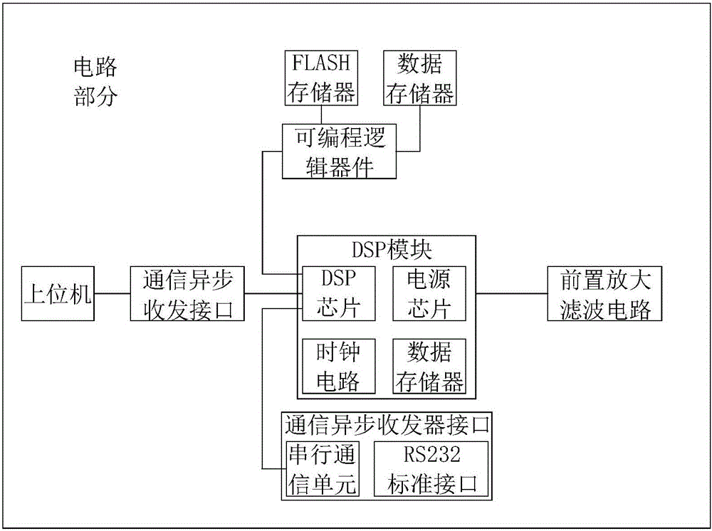
[0039] figure 2 It is a structural schematic diagram of Embodiment 2 of the present invention; image 3 It is a structural schematic diagram of the circuit part in Embodiment 2 of the present invention; Figure 4 is a partial view of the self-adaptive air outlet in embodiment 2; Figure 5 It is a partial view of the element cooling fin in Embodiment 2;
[0040] In the figure, the meanings of each reference mark are as follows: 1. Driver housing; 2. PCB circuit board; 11. Cleaning air intake device; 12. Filter device; 13. Cleaning pipeline; 14. Self-adaptive air outlet; 15 , bimetal sheet; 16, heat sink single body; 17, reflective mirror surface; 18, photosensitive switch; 19, circuit element; 20, air exhaust port; 23, insulating heat conductor;
[0041] The BYJ motor is electrically connected to the motor driver, and the motor driver includes a driver housing and a PCB board arranged in the driver housing; circuit elements are arranged on the PCB board,
[0042] The motor...
Embodiment 3
[0063] Figure 6 It is a structural schematic diagram of the heat sink in Embodiment 3 of the present invention; in the figure, the meanings of the reference signs that have appeared in the drawings used in Embodiment 2 follow the meanings in the drawings of Embodiment 2, and the newly appearing reference numerals The meanings expressed are as follows;
[0064] The difference between this embodiment and embodiment 2 is:
[0065] The individual heat sinks 16 are all arranged on an insulating heat conductor 23 , and the individual heat sinks 16 are divided along a circle.
[0066] The insulated heat conductor 23 can be an insulating layer attached to a metal material, so that the individual heat sinks 16 are insulated from each other without significantly reducing the thermal conductivity, so that the individual heat sinks 16 of the heat sink form a capacitor.
PUM
 Abstract
Description
Claims
Application Information
 - R&D
- Intellectual Property
- Life Sciences
- Materials
- Tech Scout
- Unparalleled Data Quality
- Higher Quality Content
- 60% Fewer Hallucinations
Browse by: Latest US Patents, China's latest patents, Technical Efficacy Thesaurus, Application Domain, Technology Topic, Popular Technical Reports.
© 2025 PatSnap. All rights reserved.Legal|Privacy policy|Modern Slavery Act Transparency Statement|Sitemap|About US| Contact US: help@patsnap.com


